Converter with DC link

An intermediate circuit, DC voltage technology, applied in the field of converters, can solve problems such as difficulty in realizing a space-saving and compact structure, and achieve the effects of low switching loss, reduced wire length, and low leakage inductance

Inactive Publication Date: 2017-08-22
SIEMENS AG
View PDF10 Cites 3 Cited by
  • Summary
  • Abstract
  • Description
  • Claims
  • Application Information

AI Technical Summary

Problems solved by technology

It is therefore difficult to achiev

Method used


Image

  • Converter with DC link
  • Converter with DC link
  • Converter with DC link

Examples


Example Embodiment

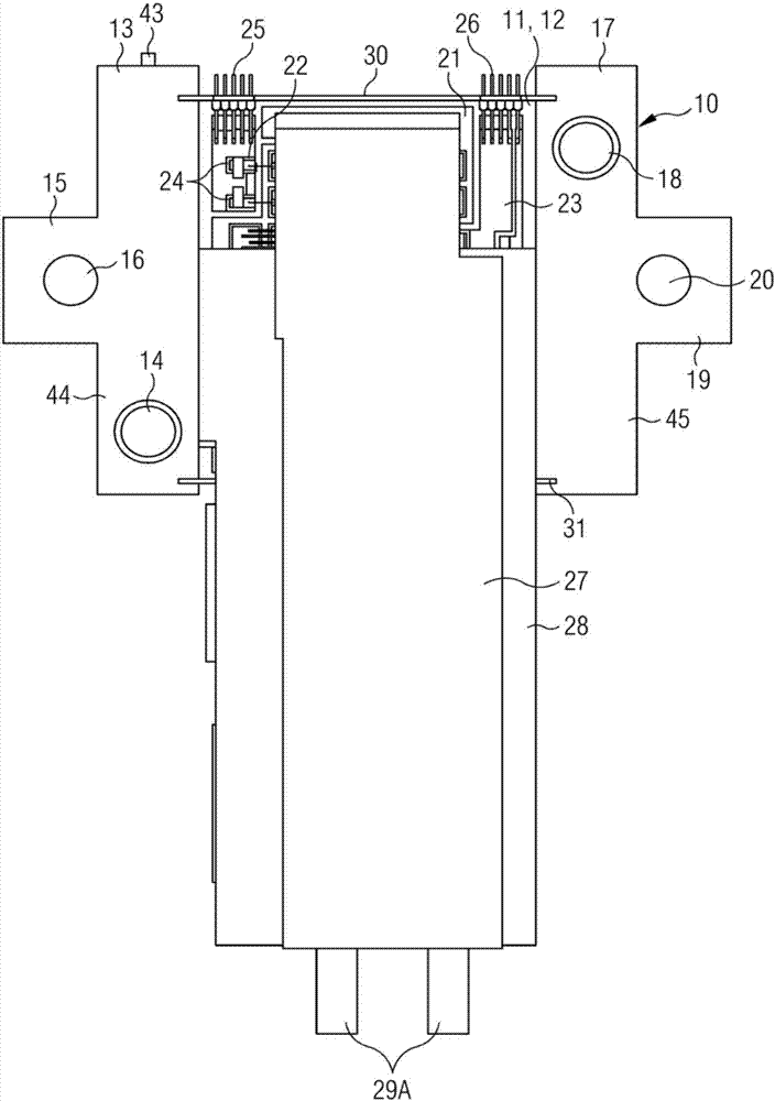
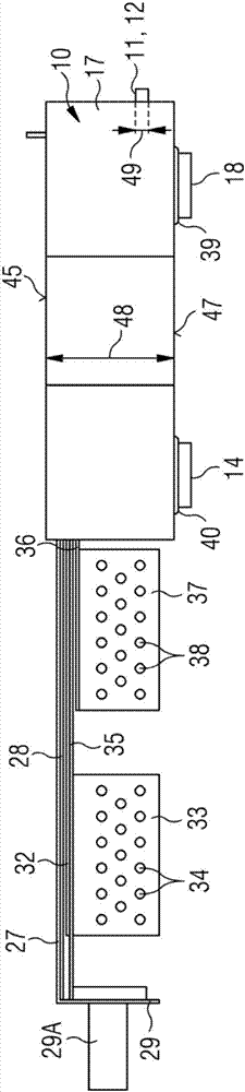
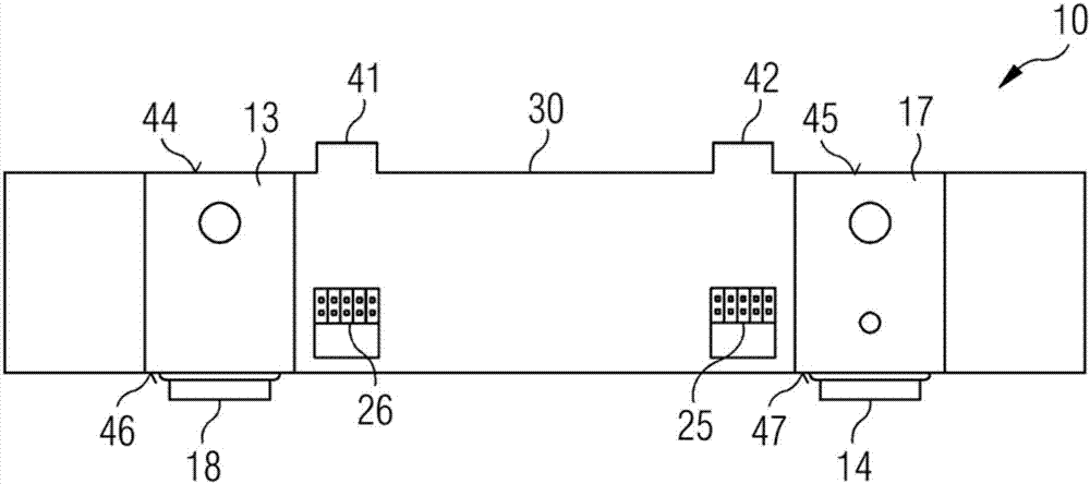
[0042] Figure 1 to Figure 6 An embodiment of the module 10 according to the present invention is shown. The modules can be used in a converter with a DC voltage intermediate circuit according to the present invention in a way that they can be stacked individually or on top of each other to form a module complex. The converter is used to convert the input voltage into an alternating voltage with a predetermined amplitude and frequency to control a single-phase or multi-phase load not shown in the figure.

[0043] In the drawings, the same elements are marked with the same reference signs.

[0044] figure 1 A top view of the module 10 is shown. The module 10 includes a ceramic heat sink 11 with a receiving surface 12. in figure 1 In the view, the receiving surface 12 extends parallel to the plane of the drawing. Conductive areas 21, 22, 23 are arranged on the receiving surface 12, and a large number of electronic components 24 are arranged on the conductive areas. The electronic ...


PUM

PropertyMeasurementUnit
Thicknessaaaaaaaaaa
Thicknessaaaaaaaaaa

Abstract

A converter with a DC link for converting an input voltage into an alternating voltage with a pre-determined amplitude and frequency for driving a single or multiple-phase load may include a number of modules which are stackable over one another. Each module may have a ceramic cooling body with a receiving surface on which electronic components of one phase are mounted, wherein the ceramic cooling body has channel(s) in the region of the receiving surface for carrying a coolant during the operation of the converter The converter may include a DC link capacitor and input-side and output-side power connections arranged on a first carrier having a arranged perpendicular to the receiving surface. The converter may also include a control unit for driving the electronic components of the phase, the control unit being arranged on a second carrier having a main plane arranged perpendicularly to the plane of the receiving surface.

Description

technical field [0001] The invention relates to a converter with a DC voltage intermediate circuit (the DC voltage intermediate circuit may also be referred to as an "intermediate DC link") for converting an input voltage into an alternating voltage with a predetermined amplitude and frequency for controlling a unit phase or multiphase loads. Background technique [0002] The power modules of current converters are cooled by means of air-cooled or water-cooled heat sinks made of a material with good thermal conductivity, for example aluminum. In order to conduct better heat conduction with the heat sink, a bracket made of copper or other materials is fixed on the heat sink with thermally conductive glue. A ceramic part provided with copper cladding on both sides is brazed on the support. The electronic components of the power module are arranged on the side of the copper-clad ceramic part facing away from the carrier. In this case, the thickness of the copper-clad ceramic...

Claims


Application Information

Patent Timeline
IPC IPC(8): H02M7/00H05K7/20
CPCH02M7/00H05K7/20H05K7/20927H05K7/14324H05K7/20254H02M7/003H05K5/0017H05K5/0021H05K5/0247H05K5/03H05K7/1432H05K7/209
Inventor L.克劳斯D.梅拉维利亚G.蒙达尔M.纽迈斯特
Owner SIEMENS AG
Why Eureka
Try Eureka