Vehicle-mounted navigation system mounting structure and engineering machine

A technology for vehicle navigation and installation structure, which is applied to radio wave measurement systems, antenna supports/installation devices, satellite radio beacon positioning systems, etc. Accuracy and other issues, to achieve the effect of reducing adverse effects, small vibration amplitude, and reducing wiring length

Active Publication Date: 2020-01-07
SHANGHAI HUAXING DIGITAL TECH
View PDF8 Cites 4 Cited by
  • Summary
  • Abstract
  • Description
  • Claims
  • Application Information

AI Technical Summary

Problems solved by technology

[0003] There are other components installed around the counterweight components. The positioning and directional antennas are respectively installed at both ends of the back of the excavator’s counterweight, which is easy to touch nearby objects and cause damage; the positioning and directional antennas are far away from the electric control cabinet in the cab. , increase the difficulty of wiring, increase the length and complexity of wiring at the same time, which is not conducive to saving costs; longer cylindrical support frames and wiring harnesses increase installation costs; when the excavator is working, the whole machine will produce severe vibrations. The support frame will inevitably increase the level of vibration of the antenna's horizontal position, thereby reducing the positioning and orientation accuracy

Method used


Image

  • Vehicle-mounted navigation system mounting structure and engineering machine
  • Vehicle-mounted navigation system mounting structure and engineering machine
  • Vehicle-mounted navigation system mounting structure and engineering machine

Examples


Embodiment 1

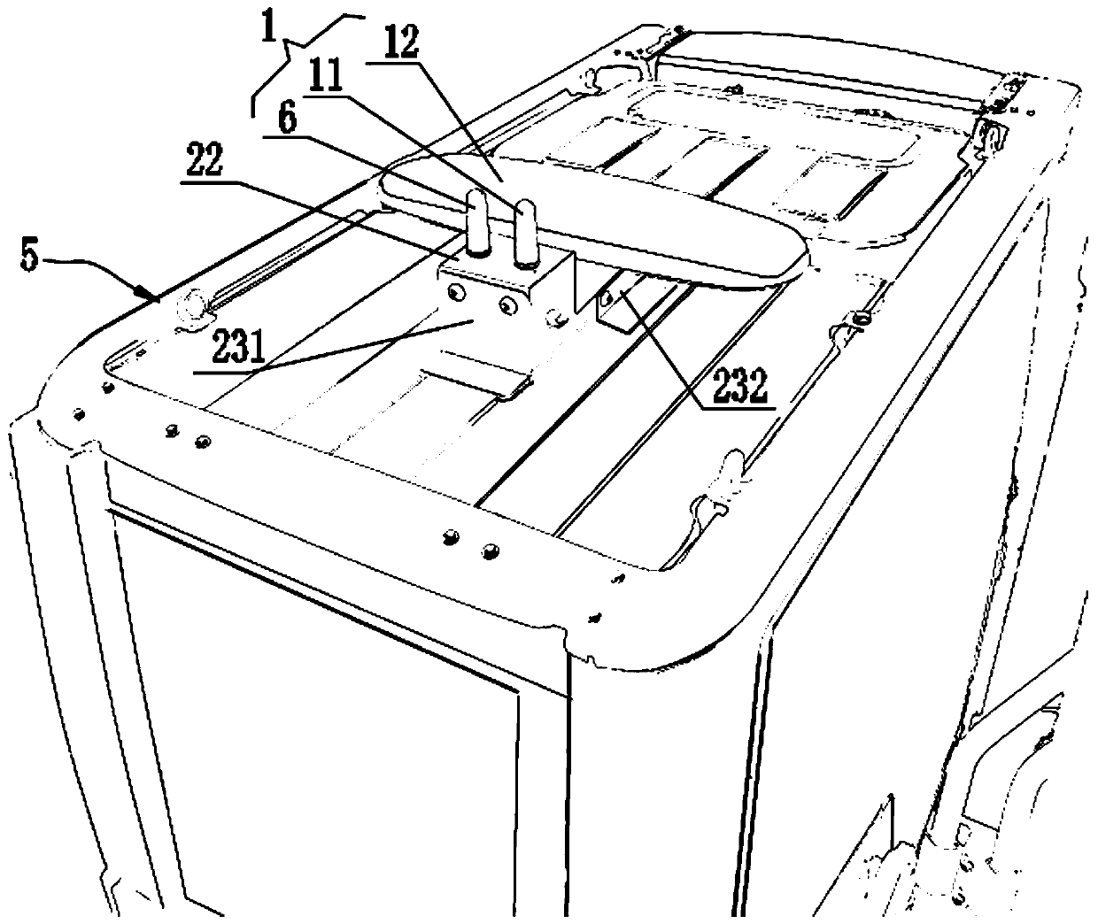
[0039] see Figure 1 to Figure 3 , a preferred embodiment of the present invention discloses an installation structure of a vehicle navigation system, which is installed on the roof of a construction machine, and the construction machine refers to an excavator, a rock drilling jumbo, a rotary excavator or other Construction machinery equipped with on-board navigation systems.

[0040] The installation structure of the vehicle navigation system includes a vehicle navigation system 1 and a mounting base 2 fixedly connected to the roof, and the vehicle navigation system 1 is installed on the mounting base 2 .

[0041]The vehicle navigation system 1 includes a radio station 11 and a GNNS receiver 12. The GNNS receiver 12 is equipped with a directional antenna and a positioning antenna, and the directional antenna is a preset distance away from the positioning antenna. Specifically, the GNNS receiver 12 has a housing, and the directional antenna and the positioning antenna are fix...

Embodiment 2

[0050] see Figure 1 to Figure 3 , another embodiment of the present invention discloses an installation structure of a vehicle navigation system, which includes a vehicle navigation system 1 and a mount 2 fixedly connected to the roof of the vehicle. The structure and positional relationship of this embodiment are basically consistent with Embodiment 1, the differences are:

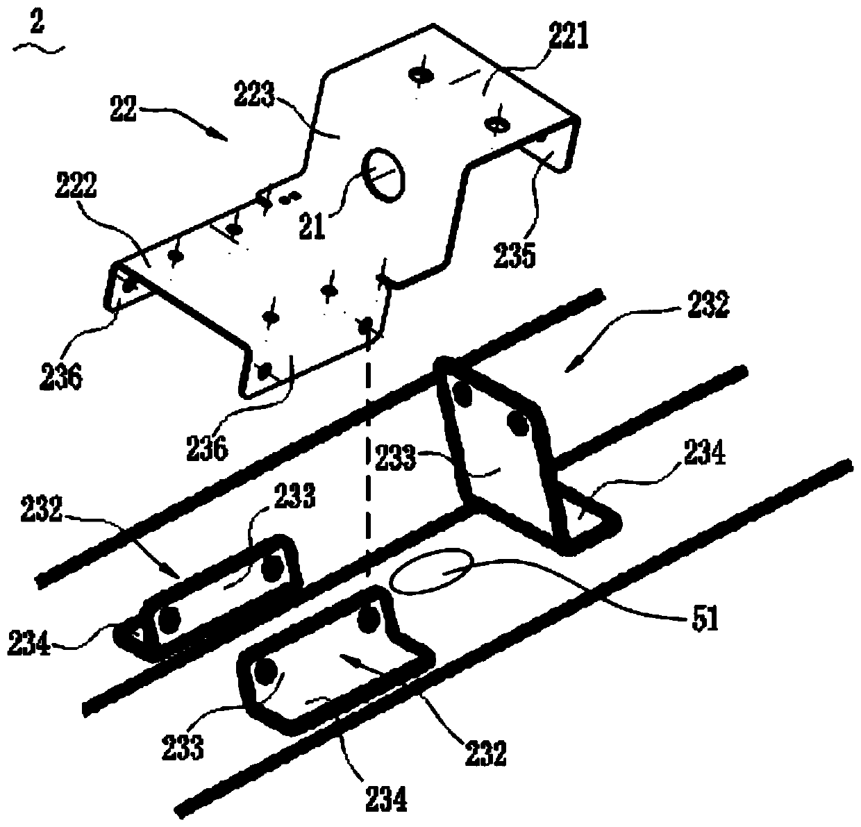
[0051] The mounting seat 2 includes a seat plate 22 and three supporting legs, the three supporting legs are fixed on the roof, and the three supporting legs are fixedly connected to the bottom of the seat plate 22 .

[0052] Further, the seat plate 22 is stepped, including an upper mounting plate 221, a lower mounting plate 222 and a connecting plate 223 connecting the upper mounting plate 221 and the lower mounting plate 222, the upper mounting plate 221 and the lower mounting plate 222 are The lower mounting plate 222 is arranged horizontally, and the upper mounting plate 221 is higher than the level...

Embodiment 3

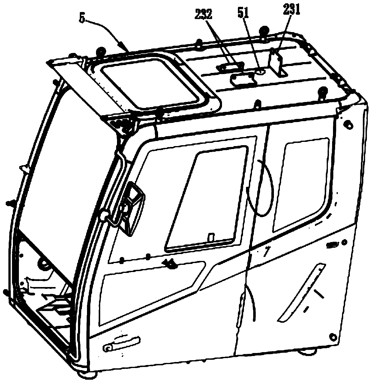
[0062] see Figure 1 to Figure 3 , the third embodiment of the present invention discloses a construction machine, which includes a cab 5 and the installation structure of the vehicle navigation system of the above-mentioned embodiment 1 or embodiment 2, the installation structure of the vehicle navigation system is located in the cab 5 The top of the cab 5 is provided with a through hole 51 for wiring, the cab 5 is equipped with an electric control cabinet (not shown), and the wiring harness of the vehicle navigation system 1 passes through the through hole 21 and The through hole 51 is connected with the electric control cabinet.

[0063] Compared with other installation positions, the vibration amplitude of the cab 5 of construction machinery is relatively small. In this embodiment, the vehicle navigation system 1 is installed on the top of the cab 5, which can minimize the vibration of the vehicle body to the vehicle navigation system 1. In addition, the vehicle navigatio...


PUM


Abstract

The invention discloses a vehicle-mounted navigation system mounting structure and an engineering machine, and belongs to the field of engineering machinery. The mounting structure comprises a vehicle-mounted navigation system and a mounting seat, wherein the vehicle-mounted navigation system comprises a radio station and a GNNS receiver, the GNNS receiver is internally provided with a directionalantenna and a positioning antenna, the mounting seat is provided with a mounting surface which is higher than the top of a vehicle, the mounting surface is provided with through holes for wiring, theradio station and the GNNS receiver are both fixedly mounted on the mounting surface, and wiring harnesses undergo wiring through the through holes. According to the mounting structure and the engineering machine, the directional antenna and the positioning antenna are arranged inside the GNNS receiver, other objects can be prevented from mistakenly touching the directional antenna and the positioning antenna, the installation process is simplified, the horizontal height of the whole mounting seat is low, the horizontal shaking amplitude of the vehicle-mounted navigation system can be reduced, the navigation precision is improved, the vehicle-mounted navigation system is mounted at the top of a cab and is closer to an electric control cabinet in the cab, the wiring length can be reduced,and the cost is reduced. The invention further discloses the engineering machine using the mounting structure.

Description

technical field [0001] The invention relates to the field of engineering machinery, in particular to an installation structure of a vehicle navigation system and an engineering machinery. Background technique [0002] At present, the commonly used installation methods for excavator antennas (including positioning and directional antennas) and GNNS receivers are to install the positioning and directional antennas at the two ends of the rear of the excavator counterweight parts respectively, in order to avoid engine protection. The hood blocks its receiving signal. Generally, a cylindrical bracket is used to raise the positioning and directional antenna respectively, higher than the occluder, and the bottom of the cylindrical bracket is fixed on the counterweight panel through threaded holes and bolts. The radio antenna is installed on the roof of the cab, and the GNNS receiver is installed in the electric control cabinet inside the cab. The above-mentioned positioning antenn...

Claims


Application Information

Patent Timeline
Patent Type & Authority Applications(China)
IPC IPC(8): B60R11/02H01Q1/24G01S19/13
CPCB60R11/0258H01Q1/24G01S19/13B60R2011/004B60R2011/0078
Inventor 罗建华颜焱张士尉
Owner SHANGHAI HUAXING DIGITAL TECH
Why Eureka
Try Eureka