Chair
A technology of chairs and pressure sensors, which is applied to chairs, stools, and other seating furniture, etc. It can solve the problems of reducing comfort and increasing users' troubles, and achieves the effects of improving comfort, responding promptly, and moving quickly
- Summary
- Abstract
- Description
- Claims
- Application Information
AI Technical Summary
Problems solved by technology
Method used
Image

Examples
Example Embodiment
[0021] Example one:
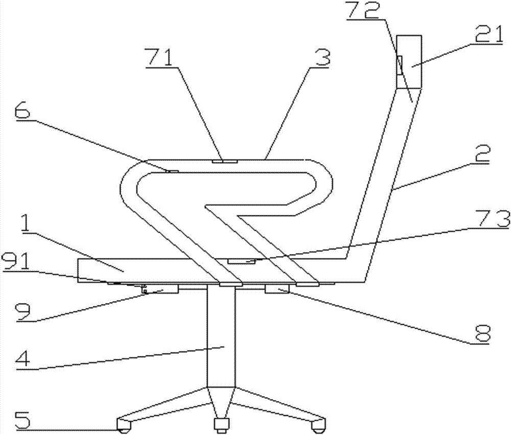
[0022] The present invention provides a chair, such as figure 1 As shown, it includes a seat cushion 1, a backrest 2, an armrest 3, a bracket 4, and a roller 5. The seat cushion 1 is arranged on the bracket 4, the backrest 2 is connected to the rear side of the seat cushion 1, and the top of the backrest 2 is provided with a headrest 21 and an armrest 3. On the left and right sides of the cushion 1, the roller 5 is installed at the bottom of the bracket 4. The bracket 4 is equipped with an electromagnetic brake for the brake of the roller 5, and the bracket 4 is equipped with a built-in power source 9, a brake switch circuit and a brake control circuit. The built-in power source 9 passes The brake switch circuit is electrically connected to the electromagnetic brake. The brake control circuit includes a control chip 8, a capacitive touch key 6 arranged on the armrest 3, a first pressure sensor 71, a second pressure sensor 72 arranged on the headrest 21 and T...
Example Embodiment
[0033] Embodiment two:
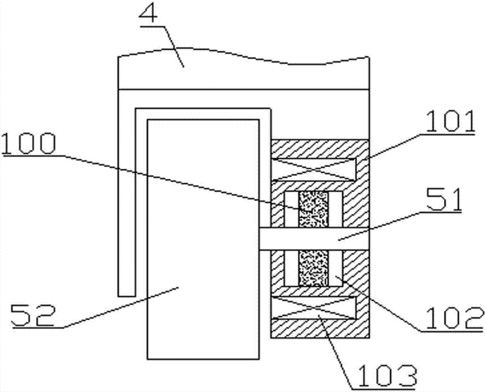
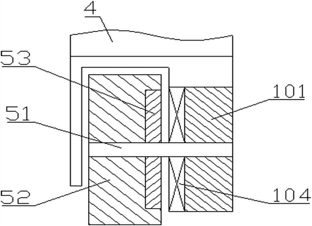
[0034] Different from the electromagnetic brake of the first embodiment, such as image 3 As shown, in this embodiment, the electromagnetic brake is an electromagnetic eddy current brake. The electromagnetic eddy current brake includes a housing 101 and an excitation coil 104 wound on the housing 101. The housing 101 is connected to the bracket 4, and the excitation coil 104 is connected to the The brake switch circuit is electrically connected. The roller 5 includes a wheel shaft 51 and a wheel body 52. The wheel shaft 51 passes through the center of the excitation reel 104 and is fixedly connected to the bracket 4. The wheel body 52 is provided with a metal ring 53, the wheel body 52 and a metal ring 53 set On the axle 51, the metal ring 53 faces the excitation coil 104. When the brake switch circuit is turned on, the coil 104 is excited to form a magnetic field. When the metal ring 53 rotates, it will cut the lines of magnetic force and generate eddy...
Example Embodiment
[0036] Embodiment three:
[0037] Different from the electromagnetic brake of the first embodiment, such as Figure 4 As shown, in this embodiment, the electromagnetic brake is an electromagnetic friction brake. The electromagnetic friction brake includes a housing 101 and an electromagnetic coil 105 wound on the housing 101. The housing 101 is connected to the bracket 4, and the electromagnetic coil 105 is connected to the The brake switch circuit is electrically connected. The roller 5 includes a wheel shaft 51 and a wheel body 52. The wheel shaft 51 is connected to the bracket 4 or the housing 101. The wheel body 52 is elastically connected with an armature 54. The armature 54 rotates with the wheel body 52, and the armature 54 faces the electromagnetic The coil 105. When the brake switch circuit is turned on, the electromagnetic coil 105 attracts the armature 54 and the armature 54 contacts and frictions with the housing 101 to achieve braking. For this reason, the part of...
PUM
 Abstract
Description
Claims
Application Information
 - Generate Ideas
- Intellectual Property
- Life Sciences
- Materials
- Tech Scout
- Unparalleled Data Quality
- Higher Quality Content
- 60% Fewer Hallucinations
Browse by: Latest US Patents, China's latest patents, Technical Efficacy Thesaurus, Application Domain, Technology Topic, Popular Technical Reports.
© 2025 PatSnap. All rights reserved.Legal|Privacy policy|Modern Slavery Act Transparency Statement|Sitemap|About US| Contact US: help@patsnap.com