Resilient four-link mechanical leg and test platform thereof

A test platform and four-link technology, applied in the field of mechanical legs, can solve the problems of large space occupation and high production cost, and achieve the effects of convenient installation and debugging, simple structure and small space occupation

Inactive Publication Date: 2016-07-13
CHONGQING UNIV
View PDF7 Cites 34 Cited by
  • Summary
  • Abstract
  • Description
  • Claims
  • Application Information

AI Technical Summary

Problems solved by technology

Affected by the running distance of the mechanical legs, the existing test platforms all have the problems of large space occupation and high production costs

Method used


Image

  • Resilient four-link mechanical leg and test platform thereof
  • Resilient four-link mechanical leg and test platform thereof
  • Resilient four-link mechanical leg and test platform thereof

Examples


Embodiment 1

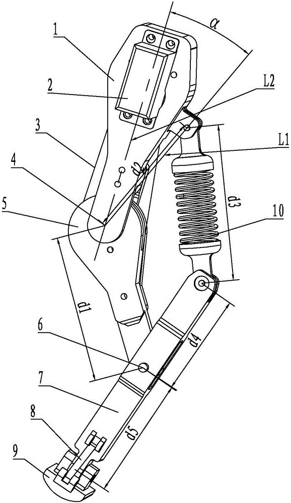
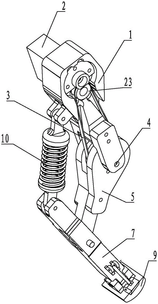
[0033] Such as figure 1 , figure 2 with image 3As shown, the present embodiment includes elongated thigh 1 and calf 5, the lower end of the thigh 1 is hinged with the upper end of the calf 5 to form a knee joint 4, and a driven wheel is fixedly connected to the calf 5, and the driven wheel The central axis coincides with the central axis of the knee joint 4 . A first motor 2 is fixed on the upper part of the thigh 1 , and a driving wheel 23 is sheathed on the output shaft of the first motor 2 , and the driving wheel 23 is connected to the driven wheel through a synchronous belt 3 . This embodiment also includes a strip-shaped foot 7 , the lower end of the lower leg 5 is hinged to the middle of the foot 7 to form an ankle joint 6 . A first damping spring 10 is connected between the upper end of the foot 7 and the upper part of the thigh 1 , and both ends of the first damping spring 10 are hinged to the thigh 1 and the foot 7 . A sole 9 is hinged at the lower end of the fo...

Embodiment 2

[0036] Such as Figure 4 with Figure 5 As shown, in addition to the elastic four-link mechanical leg structure described in the first embodiment, this embodiment also includes a relatively fixed conveyor belt 11 and a support seat 21 . Vertical guide rails 20 are installed on the support base 21 , two guide rails 20 are arranged side by side, and a first sliding block 19 is sleeved on each guide rail 20 . The same mounting block 18 is fixed on the two first sliding blocks 19 , and a driving device is connected to the mounting blocks 18 . Driven by the driving device, the mounting block 18 moves up and down along the first sliding block 19 . In this embodiment, it is preferable that the driving device includes a third motor 22, and the third motor 22 is located under the support seat 21, and the output shaft of the third motor 22 is connected with the mounting block 18 through a vertical screw nut mechanism, and the The screw nut mechanism is located between the two guide ra...


PUM


Abstract

The invention discloses a resilient four-link mechanical leg and a test platform thereof. The resilient four-link mechanical leg comprises a large leg and a small leg both in strip shapes, the lower end of the large leg is hinged to the upper end of the small leg to form a knee joint, a driven wheel is fixedly connected to the small leg, a first motor is fixed to the upper portion of the large leg, a driving wheel fixedly sleeves an output shaft of the first motor, and the driving wheel is connected with the driven wheel through a synchronous belt; the middle of a strip foot is hinged to the lower end of the small leg, and a first damping spring is connected between the upper end of the foot and the upper portion of the large leg; thus the resilient four-link mechanical leg with timely response, accurate control and effective force transmission is provided; the resilient four-link mechanical leg is disposed on a conveying belt, a supporting seat fixed relative to the conveying belt is arranged, a support rod is mounted on the supporting seat, a connecting block is fixed to the support rod, a second motor is fixed to the connecting block, an output shaft of the second motor is fixedly connected with the upper end of the large leg of the resilient four-link mechanical leg, and a mechanical leg test platform small in size and simple in structure is provided.

Description

technical field [0001] The invention belongs to the technical field of mechanical legs, and in particular relates to an elastic four-link mechanical leg and a test platform thereof. Background technique [0002] At present, due to the variety of gaits and certain obstacle-surmounting functions, footed robots have a wider range of applications than wheeled, tracked and peristaltic robots, especially in fields such as exploration and survey under complex terrain conditions. Wide range of applications. The leg structures of existing legged robots are varied, but most of them include thighs, calves and feet. The upper end of the thigh is installed on the output shaft of the power source to form a hip joint, and the lower end of the thigh is hinged with the lower leg to form a knee joint. , the knee joint is connected with a motor for realizing the rotation of the shank, and the lower end of the shank is hinged with the foot to form an ankle joint. With this structure, because ...

Claims


Application Information

Patent Timeline
Patent Type & Authority Applications(China)
IPC IPC(8): B62D57/032G01M17/00
CPCB62D57/032G01M17/00
Inventor 李奇敏任灏宇李扬宇杨壹蒋建新刘冰
Owner CHONGQING UNIV
Why Eureka
Try Eureka