Level meter

A technology of liquid level gauge and liquid level height, which is applied in the field of liquid level gauge, can solve the problems such as the inability to output the electric signal of liquid level height, and achieve the effect of simple structure, improved reading accuracy, and convenient automatic control

Inactive Publication Date: 2005-01-05
JINAN UNIVERSITY
View PDF1 Cites 32 Cited by
  • Summary
  • Abstract
  • Description
  • Claims
  • Application Information

AI Technical Summary

Problems solved by technology

[0004] The present invention mainly solves the problem that the existing magnetic tracking type liquid level gauge cannot output the electric signal of the liquid level height, and provides a liquid level gauge with high resolution, convenient installation, and the output of the electric signal of the liquid level height.

Method used


Image

  • Level meter
  • Level meter
  • Level meter

Examples


Embodiment 1

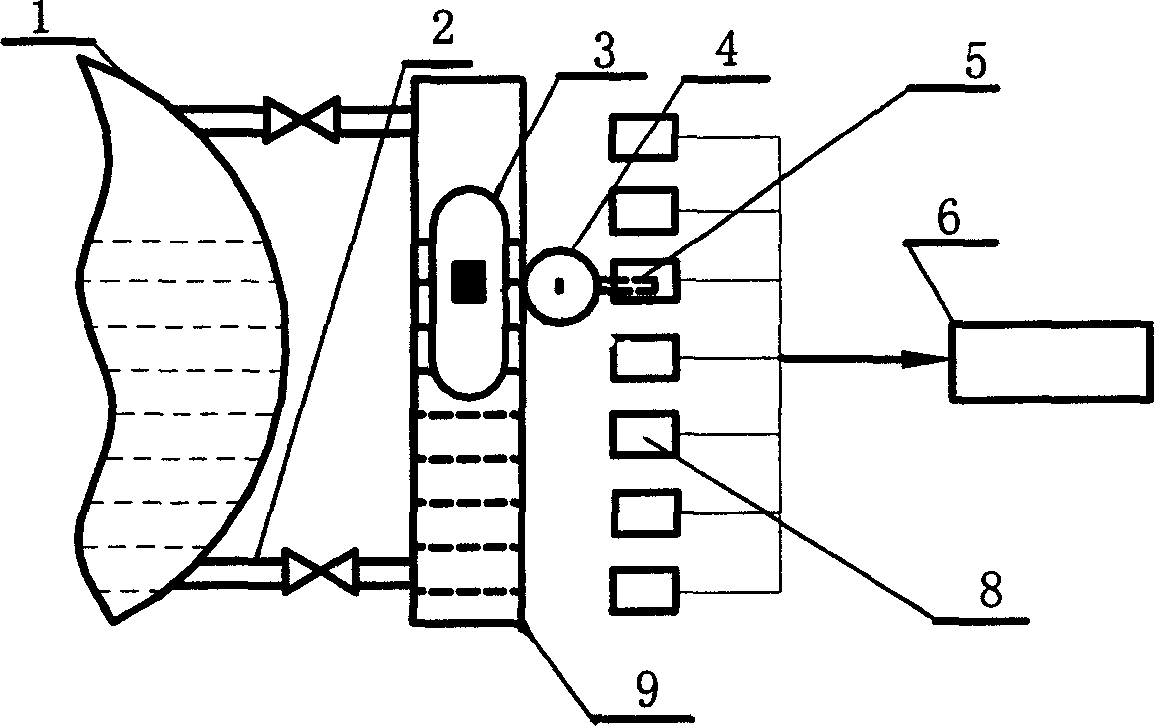
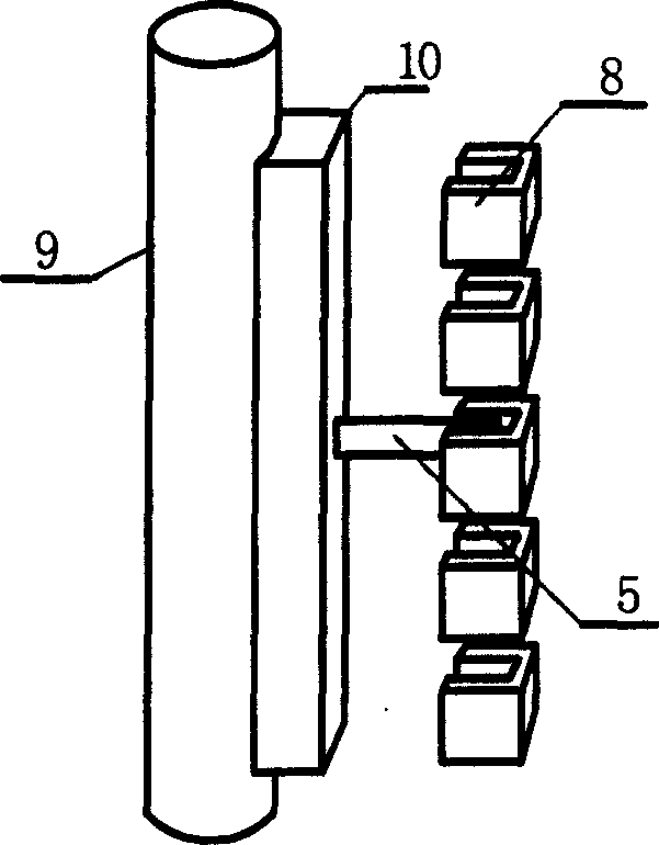
[0023] Such as figure 1 , figure 2 , Figure 4 As shown, the communicator 9 is fixed on the outside of the measured container 1 through the communicating water pipe 2 with a valve. A magnetic float 3 that rises and falls with the liquid level is arranged in the communicating device 9 . The outer wall of the connector 9 is fixed with two vertical guide rails 11. The rollers on both sides of the magnetic trolley 4 are mounted on the two guide rails 11 and can roll along the guide rails. Because the movement resistance is very small, the magnetic float 3 can drive the magnetic trolley through magnetic coupling. 4 Move flexibly along the guide rail. A vernier 5 protruding outwards is fixed on the magnetic tackle 4 . A group of transmissive photoelectric switches 8 are fixed vertically outside the connector 9, and each photoelectric switch is distributed at equal intervals; each photoelectric switch includes a pair of light-emitting diodes 13 and photoelectric receiving device...

Embodiment 2

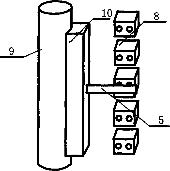
[0027] Such as figure 2 As shown, in this implementation, the photoelectric switch is a reflective photoelectric switch, and the rest are the same as in Embodiment 1. When the photoelectric switch is not affected by the cursor 5, the photoelectric receiving device 14 does not receive the light signal; The light reflected by the vernier 5 is received by the photoelectric receiving device 14, so that the height of the liquid level in the container at that time can be known.

Embodiment 3

[0029] The signal processing module diagram of the photoelectric receiving device in the control unit in this embodiment is as follows Figure 7 As shown, no light-emitting diode scanning drive module is provided, and the rest are the same as in Embodiment 1. The control unit 6 includes a CPU, a photoelectric receiving device scanning drive module 64 and a received signal processing module 63 controlled by the CPU, and a corresponding address is given to each photoelectric switch in the CPU. The light-emitting diodes 13 of the photoelectric switch group are all lit by its drive circuit. When the photoelectric receiving element 14 receives light, it is processed by the received signal processing module 63 . Driven by the photoelectric receiving device scanning driving module 64 , the groups of photoelectric receiving elements 14 send signals to the CPU one by one from bottom to top. When there is no signal at the address, the outputs are all high level; when there is a signal...


PUM


Abstract

The invention discloses a fluid level gage applied to high pressure boiler. The fluid level gage includes a connector connected to the measured container, the connector has a magnetic float elevating with the fluid level, the external side of the connector has a vernier coupled with the magnetic float, several photoelectric switches are arranged on the measured container with the fluid height, the vernier corresponds to different photoelectric switch when it is in different height, thus it is shaded and reflected; each photoelectric switch is connected to the control unit, it outputs voltage different to other photoelectric switch according to the voltage of the photoelectric switch, acquires the fluid height of the measured container. The device in the invention can provide fluid level electric signal output.

Description

Technical field: [0001] The present invention relates to liquid level gauges, especially liquid level gauges that indicate liquid level by means of floats. Background technique: [0002] For decades, boiler manufacturers in my country have used boiler water level gauges with two pieces of glass tightly joined together and fastened with bolts. The operation is not easy to distinguish, and the water level gauge is also easily polluted by water quality, which affects the observation effect. Moreover, dripping often occurs and requires frequent maintenance. , especially not suitable for high-pressure boilers. The Chinese Utility Model Patent No. 97213186.8 discloses a magnetic tracking color plate liquid level gauge, which is characterized in that the connector of the measured container is fixed on the outside of the measured container, and there is a magnetic float inside the connector that rises and falls with the liquid level , There is a magnetic color code coupled with the ...

Claims


Application Information

Patent Timeline
Patent Type & Authority Applications(China)
IPC IPC(8): G01F23/64G01F23/68
Inventor 李胜利
Owner JINAN UNIVERSITY
Why Eureka
Try Eureka