
Placing rail capable of positioning spinning roller

A roller and limit block technology, applied in tool storage devices, manufacturing tools, etc., can solve the problem of inability to position the spinning roller, and achieve the effect of increasing the anti-slip effect, facilitating the left and right movement, and increasing the stability.

Pending Publication Date: 2017-08-25
长兴宝诺纺织科技有限公司
View PDF9 Cites 0 Cited by
  • Summary
  • Abstract
  • Description
  • Claims
  • Application Information

AI Technical Summary

Problems solved by technology

[0004] The object of the present invention is to provide a placement rail that can position the spinning drum, which has the advantage of positioning the spinning drum, and solves the problem that the existing placement rail cannot position the spinning drum when it is in use

Method used

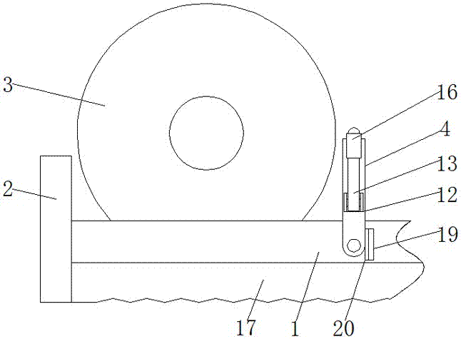
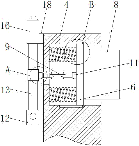
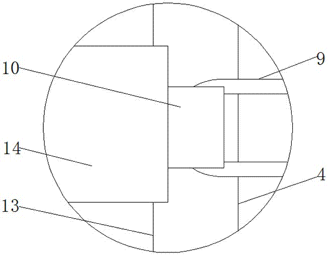

Image

  • Placing rail capable of positioning spinning roller
  • Placing rail capable of positioning spinning roller
  • Placing rail capable of positioning spinning roller

Examples


Embodiment Construction

[0018] The following will clearly and completely describe the technical solutions in the embodiments of the present invention with reference to the accompanying drawings in the embodiments of the present invention. Obviously, the described embodiments are only some, not all, embodiments of the present invention. Based on the embodiments of the present invention, all other embodiments obtained by persons of ordinary skill in the art without making creative efforts belong to the protection scope of the present invention.

[0019] see Figure 1-4 , a placement rail capable of positioning the spinning drum, comprising a placement rail body 1, the left end of the placement rail body 1 is fixedly connected to a limiting plate 2, the top of the placement rail body 1 is provided with a spinning drum body 3, and the placement rail body 1 The front surface of the hollow block 4 is movably connected with a hollow block 4, and the top of the front surface of the hollow block 4 is fixedly ...


PUM


Abstract

The invention discloses a placing rail capable of positioning a spinning roller. The placing rail comprises a placing rail body. The left end of the placing rail body is fixedly connected with a limiting plate, and the top of the placing rail body is provided with a spinning roller body. The front surface of the placing rail body is movably connected with a hollow block, and the front surface of the inner wall of the hollow block is fixedly connected with a telescopic rod. According to the placing rail capable of positioning the spinning roller, the placing rail body, the limiting plate, the spinning roller body, the hollow block, the telescopic rod, springs, a limiting block, a baffle, an iron chain, a first fixing block, a second fixing block, a positioning block, a connecting rod and a reinforcing ring are arranged to be matched for use, and thus the problem that an existing placing rail cannot position the spinning roller in the using process is solved; and the placing rail capable of positioning the spinning roller has the advantage of positioning the spinning roller, using stability of the spinning roller body is improved, and hence the placing rail can be used by users conveniently.

Description

technical field [0001] The invention relates to the technical field of placing appliances, in particular to a placing rail capable of positioning a spinning cylinder. Background technique [0002] The original meaning of textile is taken from the general term of spinning and weaving, but with the continuous development and improvement of the textile knowledge system and subject system, especially after the emergence of non-woven textile materials and three-dimensional composite weaving technologies, the current textile is not only a traditional Hand spinning and weaving, including non-woven technology, clothing, airbags, curtains and carpets in daily life are all products of textile and printing and dyeing technology. [0003] At the very beginning of weaving, it is necessary to interweave the threads together to weave cloth. When winding the thread, the spinning drum is needed, and when placing the spinning drum, the placement rail is needed. However, when the existing plac...

Claims


Application Information

Patent Timeline
Patent Type & Authority Applications(China)
IPC IPC(8): B25H3/00
CPCB25H3/00
Inventor 王振
Owner 长兴宝诺纺织科技有限公司
Learn More