
Rotor device for aircraft and aircraft

An aircraft and rotor technology, applied in the field of aircraft, can solve the problems of low total aerodynamic efficiency of blades, large difference in relative speed, large gap in aerodynamic effect, etc., and achieve the improvement of tip volatile speed, small relative speed difference, and aerodynamic performance. Efficiency improvement effect

Active Publication Date: 2019-07-19
徐丛逸
View PDF6 Cites 0 Cited by
  • Summary
  • Abstract
  • Description
  • Claims
  • Application Information

AI Technical Summary

Problems solved by technology

Therefore, when the blade rotates, the relative speed of the blade along the radial direction (10% to 100%) is very different from the air, resulting in a large gap in the aerodynamic effect;
[0009] 2. The linear velocity of the blade near the blade root is low and the efficiency is low, and the linear velocity of the blade near the blade tip is high, which is prone to shock wave stall, and the total aerodynamic efficiency of a blade is low;
[0011] 4. All the blades can only rotate around one center, which determines that the swept area of ​​the blades is a disk, resulting in the same vertical and horizontal dimensions of the helicopter.

Method used


Image

  • Rotor device for aircraft and aircraft
  • Rotor device for aircraft and aircraft
  • Rotor device for aircraft and aircraft

Examples


Embodiment Construction

[0042] In order to make the objectives, technical solutions and advantages of the present invention clearer, the technical solutions in the embodiments of the present invention will be described in more detail below in conjunction with the drawings in the embodiments of the present invention. In the drawings, the same or similar reference numerals denote the same or similar elements or elements having the same or similar functions throughout. The described embodiments are some, but not all, embodiments of the invention. The embodiments described below by referring to the figures are exemplary and are intended to explain the present invention and should not be construed as limiting the present invention. Based on the embodiments of the present invention, all other embodiments obtained by persons of ordinary skill in the art without creative efforts fall within the protection scope of the present invention. Embodiments of the present invention will be described in detail below ...


PUM


Abstract

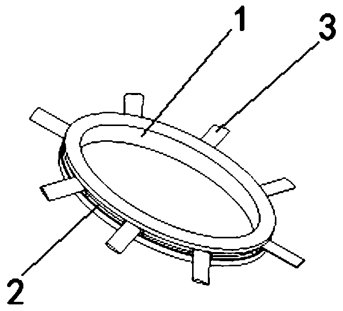
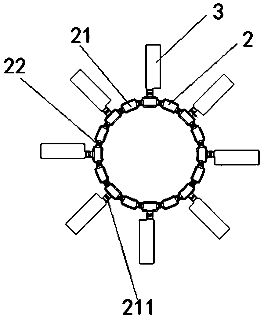
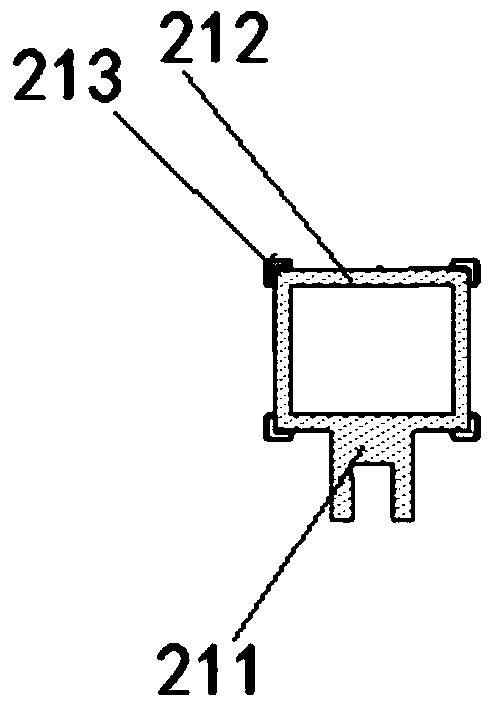
The invention discloses a rotor device for aircraft and the aircraft. The aircraft rotor device includes a driving track, a rotating mechanism and blades. The cross section of the driving track is ring-shaped with a cavity, and several coil groups are wound around the grooves on the inner wall, forming a primary like a linear drive motor, which generates a magnetic field after being energized; the rotating mechanism includes a driving unit and an elastic connector, which are connected at intervals. The drive unit is similar to the secondary of a linear drive motor, which generates a circumferential drive force under the action of the orbital magnetic field. The elastic link can be deformed in multiple directions, allowing the rotating mechanism to move along a track with variable curvature. A magnet is set on the drive unit, which levitates in the orbital magnetic field; the paddle is installed on the drive unit, and moves along the drive track to generate aerodynamic force. The invention provides a rotor device for an aircraft, the blades can move along a non-circular orbit, the average length of the blades has high aerodynamic efficiency, and the design of the aerodynamic layout is easy, which provides a new option for new configuration rotor aircraft.

Description

technical field [0001] The invention relates to the technical field of aircraft, in particular to a rotor device for an aircraft and the aircraft. Background technique [0002] Rotor (blade) technology is mainly used in helicopters and propeller aircraft, among which helicopters are the most widely used. [0003] Helicopter rotors generally consist of a hub and blades. The center of the hub is connected to a rotating main shaft, and the blades are connected to the arms of the hub. The number of blades varies. [0004] The helicopter drives the rotor blades to rotate by driving the main shaft, and the relative motion speed between the blades and the air generates lift. At a certain rotational angular velocity, the radius near the tip of the blade is large, and the linear velocity relative to the air is large and the lift is large. By controlling the direction of the lift force of the rotor disc, the helicopter can fly forward, backward, left or right. [0005] The helicopt...

Claims


Application Information

Patent Timeline
Patent Type & Authority Patents(China)
IPC IPC(8): B64C27/10B64C27/12B64C27/20
CPCB64C27/10B64C27/12B64C27/20B64U10/10B64U30/20
Inventor 徐丛逸
Owner 徐丛逸
Learn More