
Excavator bucket hook

A technology for excavators and bucket teeth, applied in the field of excavators, can solve problems such as reducing driving efficiency, and achieve the effects of reducing wear, reducing motion paths, and prolonging service life

Inactive Publication Date: 2017-08-25
永平县建达鑫鑫合金铸造有限公司
View PDF5 Cites 2 Cited by
  • Summary
  • Abstract
  • Description
  • Claims
  • Application Information

AI Technical Summary

Problems solved by technology

However, for composite strata, that is, the composite layer of concrete layer or rock layer and soil layer, the soil layer is located under the high-hardness concrete layer or rock layer. When the excavator is digging, the bucket hook will reduce the driving efficiency

Method used


Image

  • Excavator bucket hook
  • Excavator bucket hook

Examples


Embodiment 1

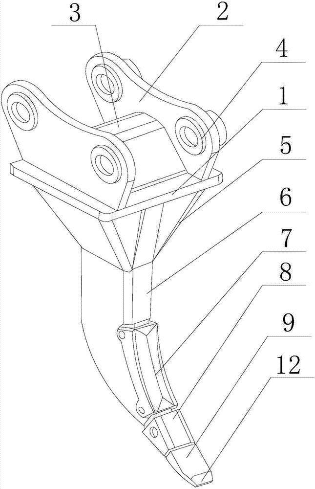
[0024] Such as figure 1 As shown in Figure 3, this embodiment includes a mounting plate 1, on both sides of the upper part of the mounting plate 1, ear plates 2 with shaft holes 4 are installed, and a trapezoidal reinforcing plate is welded between the two ear plates 2 3. Weld an arc-shaped gear bar 6 with bucket teeth 9 at the middle of the bottom of the mounting plate 1, and a reinforcement plate is welded between the square surrounding edges of the mounting plate 1 and the outer wall of the gear bar 6 5. A sheath 7 is installed through a pin shaft on the inner side of the arc-shaped curved surface of the tooth bar 6, and a gear sleeve 8 is installed on the upper part of the bucket tooth 9 through a pin shaft, and a main flow groove is opened on the back of the bucket tooth 9 10. There are auxiliary diversion grooves 11 symmetrically on both sides of the main diversion groove 10, and the auxiliary diversion grooves 11 extend obliquely outward along the direction from the bot...


PUM


Abstract

The invention discloses an excavator bucket hook. The excavator bucket hook comprises a mounting plate. Lug plates with shaft holes are installed at the two sides of the upper portion of the mounting plate. An arc-shaped toothed bar with bucket teeth is welded to the middle position of the bottom of the mounting plate. The inner side of an arc-shaped curved surface of the toothed bar is provided with a protecting bush through a pin shaft. A gear sleeve is installed on the upper portions of the bucket teeth through a pin shaft. A main flow guide groove is formed in the back faces of the bucket teeth. Auxiliary flow guide grooves are symmetrically formed in the two sides of the flow guide groove and obliquely extend outwards in the direction pointing to the bottom of the gear sleeve from the bottoms of the bucket teeth. Sealing edges perpendicular to the axes of the auxiliary flow guide grooves are arranged on the two side walls of the auxiliary flow guide grooves, and a gap is reserved between the two sealing edges. When the bucket teeth are cut into a soil layer, the two auxiliary flow guide grooves are symmetrically formed in the two sides of the main flow guide groove and obliquely extend outwards in the direction pointing to the bottom of the gear sleeve from the bottoms of the bucket teeth, a rectangular column and two tilted T-shaped pillars are produced on the cut-off surface of the soil layer, and sudden descending of the bucket teeth in the smashing process is avoided.

Description

technical field [0001] The invention relates to an excavator, in particular to an excavator bucket hook. Background technique [0002] Excavator rippers are also called bucket hooks, which are generally single teeth, but also have two or three teeth, and have strong digging and cutting force. It is suitable for crushing and splitting hard soil, semi-hard rock and weathered rock, so as to facilitate digging and loading operations with buckets. Bucket teeth are consumable parts in the working process of the excavator, especially the tooth tip, when it contacts with the contact material at high speed, the impact force is relatively strong. If the strength is relatively low, the tooth tip is prone to deformation. With the increase of the excavation depth The relative movement with the material will produce a positive extrusion force on the entire surface of the bucket teeth, especially when excavating rocky materials, the friction between the bucket teeth and the material is gr...

Claims


Application Information

Patent Timeline
Patent Type & Authority Applications(China)
IPC IPC(8): E02F5/32E02F9/28
CPCE02F5/32E02F9/2808E02F9/2833E02F9/285E02F9/2875
Inventor 羊实
Owner 永平县建达鑫鑫合金铸造有限公司
Learn More