Solar cell panel

a solar cell and panel technology, applied in the field can solve the problems of reducing the output power reducing the efficiency of solar cell panels, and reducing the cost of conductive adhesive films, so as to reduce the movement path of carriers, improve the output of solar cell panels, and reduce the effect of a small width

Active Publication Date: 2019-12-17
SHANGRAO JINKO SOLAR TECH DEV CO LTD
View PDF19 Cites 0 Cited by
  • Summary
  • Abstract
  • Description
  • Claims
  • Application Information

AI Technical Summary

Benefits of technology

[0009]Therefore, embodiments of the present invention have been made in view of the above problems, and the present invention is to provide a solar cell panel having enhanced output power and being made by a simple process.
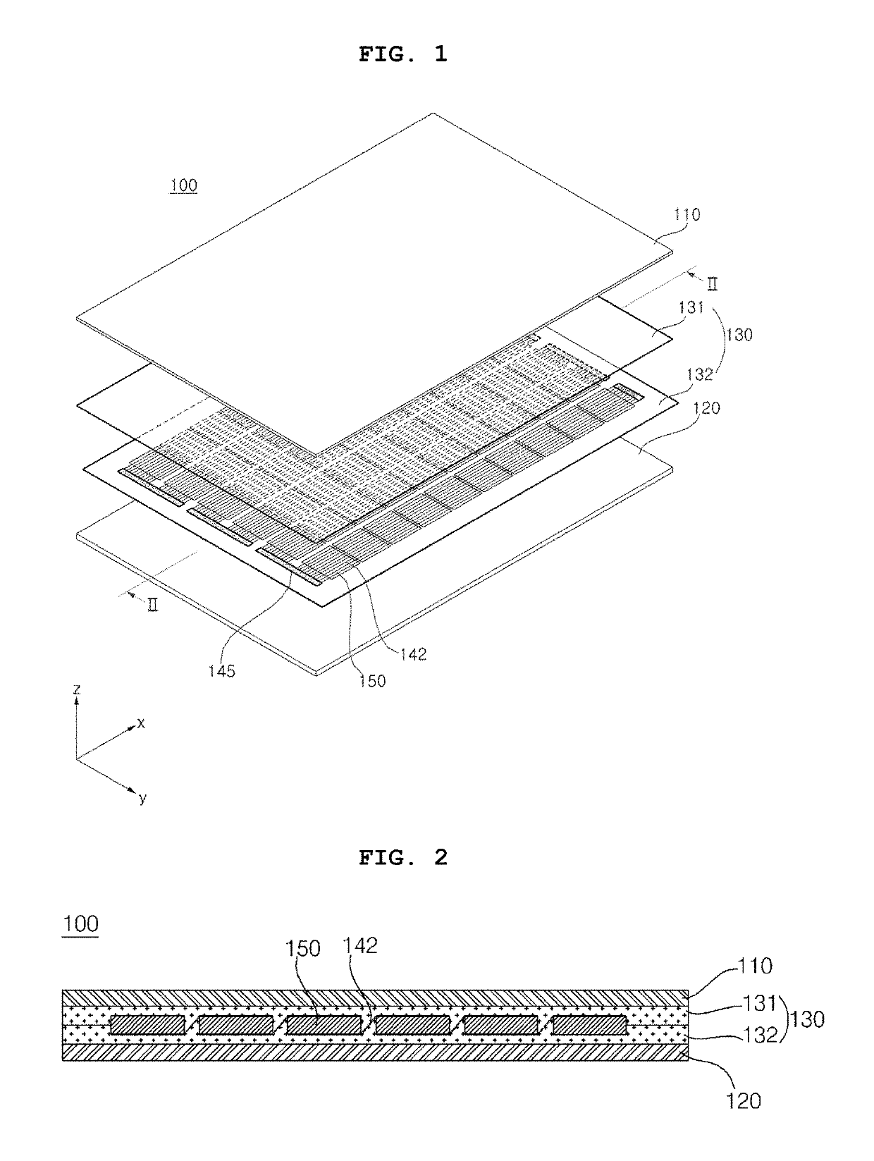
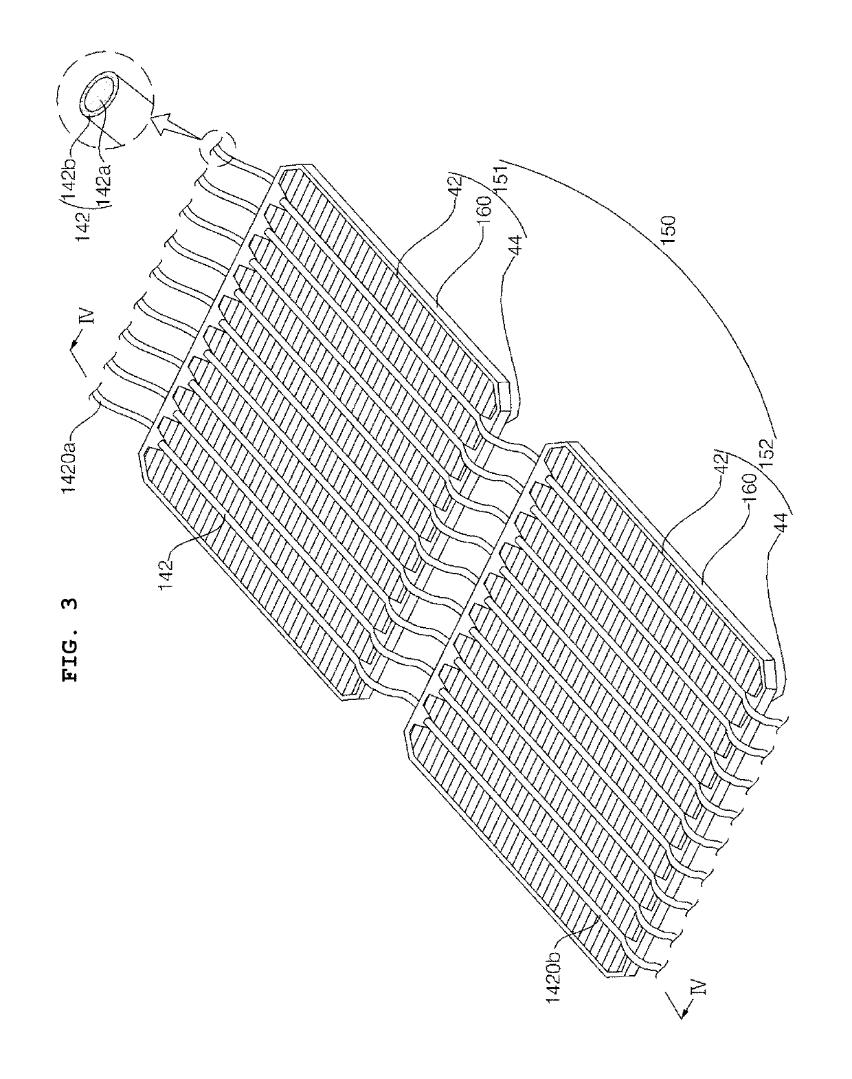
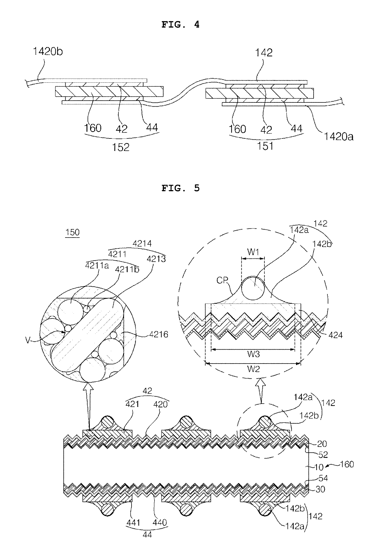
[0011]According to this embodiment, an output of a solar cell panel can be improved through reducing a movement path of carriers by a large number of leads having a small width. Also, the leads have a circular cross-section, and thus, light loss can be minimized by diffuse reflection, and the output of the solar cell panel can be further improved. By applying the leads to a solar cell including a conductivity type region having a crystal structure different from that of a semiconductor substrate, the leads can be stably electrically connected to the solar cell, even if an alignment error of the leads having the small width occurs.
[0012]In this instance, the lead can be attached by a simple process to have a simple structure through using a solder layer. In this instance, at least one of first and second metal electrode layers includes metal particles and a cross-linking resin to prevent the solder layer from penetrating into the at least one of the first and second metal electrode layers, thereby improving reliability of the solar cell panel.

Problems solved by technology

Then, shading loss may be generated due to such a great width of the ribbons.
As a result, there is a limitation in enhancing output power of a solar cell panel.
However, the conductive adhesive films are expensive.
Also, the conductive adhesive films are positioned between the electrodes of the solar cell and the ribbons, respectively, and thus, the process of attaching the ribbons to the electrodes of the solar cell is complicated.
More particularly, if a large number of interconnectors having widths smaller than widths of the ribbons are used, instead of the ribbons, in consideration of light loss, process cost and time may largely increase when the conductive adhesive films are used.

Method used


Image

  • Solar cell panel
  • Solar cell panel
  • Solar cell panel

Examples


experimental example 1

[0148]A metal electrode layer was formed by coating a low-temperature paste and heat-treating the same. The low-temperature paste included metal particles, a cross-linking resin, a hardener, and a solvent. The metal particles included spherical-shaped particles having a size of 0.1 to 5 um, and flake-shaped particles having a long width of 2 to 10 um and a thickness of 0.2 to 5 um. In this instance, the spherical-shaped particles were included by 80 parts by weight and the flake-shaped particles were included by 20 parts by weight with respect to 100 parts by weight of the metal particles. The cross-linking resin was an epoxy-based resin, the hardener was an amine-based hardener, and the solvent was butyl carbitol acetate. With respect to 100 parts by weight of a sum of the metal particles and the cross-linking resin, the metal particles were included by 80 parts by weight, the cross-linking resin was included by 20 parts by weight, and the hardener was included 2 parts by weight, t...

experimental example 2

[0150]Pull strength was measured by the method same as the method in Experimental Example 1 except that the lead including a second solder layer of SnBi instead of the first solder layer was attached by the tabbing process.

experimental example 3

[0151]Pull strength was measured by the method same as the method in Experimental Example 1 except that the lead including a third solder layer of SnIn instead of the first solder layer was attached by the tabbing process.


PUM


Abstract

A solar cell panel includes a first solar cell and a second solar cell; and a plurality of leads connecting the first solar cell and the second solar cell. Each of the first solar cell and the second solar cell includes: a first electrode including a plurality of finger lines in a first direction and a plurality of first bus bars in a second direction crossing the first direction; and a second electrode including a plurality of second bus bars in the second direction. The plurality of leads have a diameter or width of 100 to 500 μm, and include 6 or more leads arranged at one surface side of the first or second solar cell. The plurality of leads are connected to the plurality of first bus bars of the first solar cell and the plurality of second bus bars of the second solar cell by a solder layer, respectively.

Description

CROSS-REFERENCE TO RELATED APPLICATIONS[0001]This application claims the priority benefit of Korean Patent Applications No. 10-2016-0036715 filed on Mar. 28, 2016 and No. 10-2016-0164404 filed on Dec. 5, 2015 in the Korean Intellectual Property Office, the disclosures of all of which are incorporated herein by reference.BACKGROUND OF THE INVENTION[0002]Field of the Invention[0003]Embodiments of the present invention relate to a solar cell panel, and more particularly, to a solar cell panel including solar cells electrically connected to each other.[0004]Description of the Related Art[0005]Recently, as existing energy resources such as petroleum and coal are depleted, interest in alternative energy sources is increasing. In particular, a solar cell is highlighted as a next-generation cell capable of converting solar energy into electric energy.[0006]A plurality of solar cells are connected in series or in parallel by a plurality of ribbons, and are then packaged through a packaging p...

Claims


Application Information

Patent Timeline
Patent Type & Authority Patents(United States)
IPC IPC(8): H01L31/02H01L31/0224H01L31/048H01L31/05H01L31/0747H01L31/075
CPCH01L31/0504H01L31/0747H01L31/0512H01L31/022425H01L31/022466H01L31/02013H01L31/0481H01L31/022433H01L31/075H01L31/0201Y02E10/50Y02E10/548
Inventor LEE, JINHYUNGHA, JUNGMINPARK, SANGWOOK
Owner SHANGRAO JINKO SOLAR TECH DEV CO LTD
Why Eureka
Try Eureka