Self-suction microfluid fuel cell based on paper-wrapped electrode

A fuel cell and self-priming technology, which is applied in the direction of aqueous electrolyte fuel cells, fuel cell additives, battery electrodes, etc., can solve the problems of limiting the application of microfluidic fuel cells, increasing system complexity, and low flow rate of reaction liquid, etc., to achieve The effect of shortening the ion movement path, reducing internal resistance, and increasing the reaction area

Active Publication Date: 2021-03-26
JIANGSU UNIV OF TECH
View PDF9 Cites 0 Cited by
  • Summary
  • Abstract
  • Description
  • Claims
  • Application Information

AI Technical Summary

Problems solved by technology

The existence of external pumps increases the complexity of the system and limits the application of microfluidic fuel cells in portable electronic devices
In order to get rid of the limitation of external pumps, in recent years, researchers have proposed to install microfluidic fuel cells in paper-based materials. Relevant studies have shown that the automatic feeding of reaction liquid can be realized by using capillary action, and a stable flow can be formed in the paper-based flow channel. Laminar flow, but the designed paper-based microfluidic fuel cell generally has a large internal resistance, and the flow rate of the reaction solution in the paper-based flow channel is low

Method used


Image

  • Self-suction microfluid fuel cell based on paper-wrapped electrode
  • Self-suction microfluid fuel cell based on paper-wrapped electrode
  • Self-suction microfluid fuel cell based on paper-wrapped electrode

Examples


Embodiment Construction

[0025] The present invention will now be described in detail with reference to the drawings. This figure is a schematic diagram of the present invention, and therefore only the configurations related to the present invention are shown in schematic.

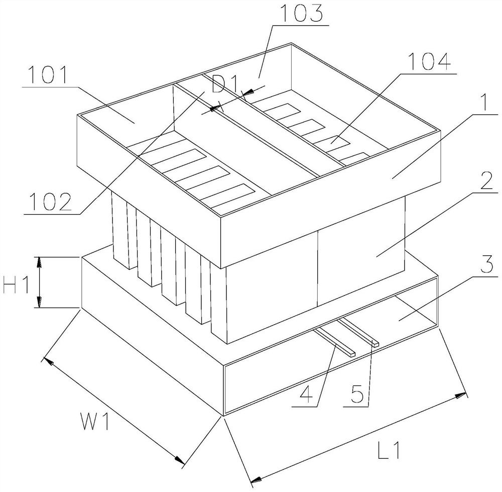
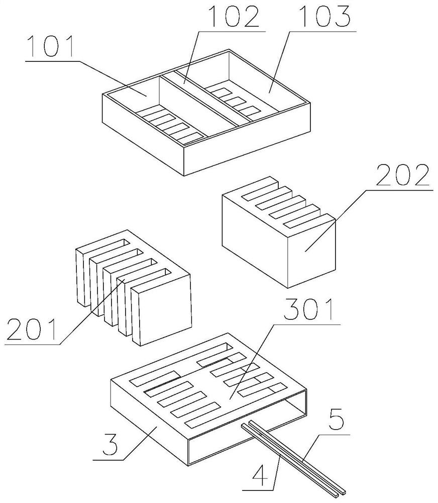
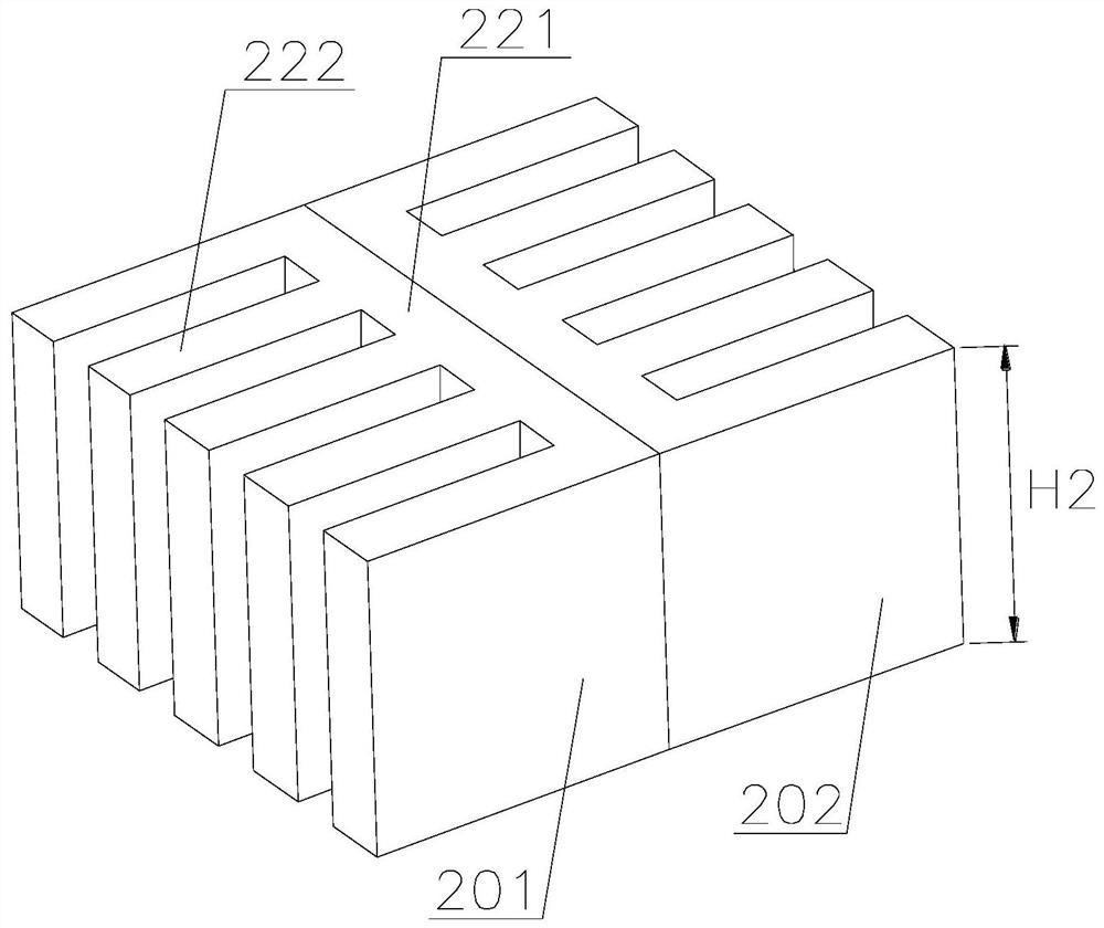
[0026] Such as Figure 1-4 As shown, the present invention is a self-suction microfluidic fuel cell based on a paper-packet electrode comprising a reservoir 1, a paper bag electrode 2, and an absorbing box 3 disposed from top, and the paper packet electrode 2 comprises an anode. 201 and cathode 202, the anode 201 and the cathode 202 are bonded to each other, and the anode 201 and the cathode 202 are graphite core 211, the anode 201 and the outer wall surface of the anode 201 and the cathode 202 coated with a porous filter paper 213, the anode 201 Including the main body portion 221, the anode 201 main body portion 221 extends with a comb teeth 222 from one side of the cathode 202, which is the same as the anode 201, and the cathode 202...


PUM

PropertyMeasurementUnit
thicknessaaaaaaaaaa
heightaaaaaaaaaa
thicknessaaaaaaaaaa

Abstract

The invention provides a self-suction microfluid fuel cell based on a paper-wrapped electrode. The cell comprises a liquid storage tank, a paper-wrapped electrode and an absorption tank which are sequentially arranged from top to bottom, the paper-wrapped electrode comprises an anode and a cathode, the anode and the cathode are attached to each other, graphite cores are arranged in the anode and the cathode, and the outer wall surfaces of the anode and the cathode are coated with porous filter paper. The anode comprises a main body part, one side, far away from the cathode, of the anode main body part extends to form a comb tooth part, the cathode and the anode have the same structures, the extension direction of the comb tooth part on the cathode is opposite to that of the comb tooth parton the anode, the outer wall surfaces of the comb tooth parts of the anode and the cathode are coated with catalyst layers, and the catalyst layers are arranged inside the porous filter paper. The porous filter paper on the outer vertical surface of the paper-wrapped electrode main body part is attached to the high-conductivity electrolyte to form an ion motion channel in the fuel cell, so that fuel diffusion is effectively controlled, parasitic current is prevented from being generated, the distance between the cathode and the anode is reduced, an ion motion path is shortened, and the internal resistance of the fuel cell is reduced.

Description

Technical field [0001] The present invention relates to the field of fuel cell technology, and more particularly to a self-suction microfluidic fuel cell based on a paper bag electrode. Background technique [0002] The fuel cell is a power generation device having a chemical energy having a fuel into an electrical energy, and the principle of fuel cell is an electrochemical device, which composition is the same as that of the general battery. Its monomer battery consists of two electrodes (negative electrodes, i.e., fuel electrodes, and positive electrodes, oxidant electrodes), and electrolyte. Different, the active material of the general battery is stored inside the battery, and therefore, the battery capacity is limited. The positive and negative electrode itself does not contain an active substance, only a catalytic conversion element. Therefore, the fuel cell is actually converted into an energy conversion machine that can be converted into electrical energy. When the batte...

Claims


Application Information

Patent Timeline
Patent Type & Authority Applications(China)
IPC IPC(8): H01M4/86H01M4/96H01M8/04276H01M8/08
CPCH01M8/04276H01M8/08H01M4/96H01M4/8657H01M4/8605Y02E60/50
Inventor 李丽贝绍轶李波郑焱
Owner JIANGSU UNIV OF TECH
Why Eureka
Try Eureka