Light-Emitting Component and Method for The Production Thereof

a technology of light-emitting components and light-emitting components, which is applied in the direction of electrical equipment, semiconductor devices, organic semiconductor devices, etc., can solve the problems of high light density, large reduction of quantum efficiency, and high accumulation of excitons in their main formation zone, and achieve high efficiency

Active Publication Date: 2011-06-30
NOVALED GMBH
View PDF4 Cites 33 Cited by
  • Summary
  • Abstract
  • Description
  • Claims
  • Application Information

AI Technical Summary

Benefits of technology

[0027]The invention has the object to provide an improved light-emitting component with high efficiency even at high light densities as well as a method for the production thereof.
[0031]Another important advantage of the invention is the easier production of the component as, thanks to the mixing of the emitters, fewer layers are to be applied.
[0048]An advantageous embodiment of the invention provides for a minimum energy of singlet excitons and triplet excitons in the hole blocking layer or in the electron blocking layer being higher than a minimum energy of singlet excitons and triplet excitons in the emission layer.
[0073]It is essential that the diffusion on the lattice of emitter dyes is effectively prevented. The diffusion is suppressed by the substructure of the emission layer which limits the excitons in their diffusion. The substructures are not required to efficiently capture charges in order to, for example, increase the recombination efficiency and thus the absolute electroluminescence efficiency (Cheng et al., Jpn. J. Appl. Phys. 42 (2003) L376). It is instead attempted to enclose the emitter dyes in zones which are spatially surrounded by a material whose triplet energy—similar to that of the conventional blocker layers—is high in comparison to the triplet energy of the emitter dye. In this connection, the actual concentration of the emitter dyes in these zones is not reduced to allow for an efficient energy transfer of the host excitons to the emitter. It is exploited that the diffusion process is a statistical process without any preferred direction and that furthermore each diffusion step to a neighboured molecule is not influenced by the previous step. By introducing energetic barriers which prevent a diffusion of the excited state in this direction, the actual probability of the diffusion in favour of the radiating recombination of the excitons, i.e. while emitting light, is thus reduced. Neighboured exciton sublayer structures are arranged further from each other than the mean interaction range typical according to Dexter, i.e. at least about 1 to about 2 nm, depicts.
[0086]In an advantageous implementation of the invention, it can be provided for the concentration of the at least one phosphorescent emitter dye in the at least one host material within the mixed systems being between 0.1% by mole and 50% by mole. 0.1% by mole guarantees an efficient transfer of the excitons from the host or matrix material to the emitter dye and more than 50% by mole markedly reduces the efficiency of the emission by means of aggregation.
[0093]Energy transfer processes between different emitter dyes are suppressed for the generation of white light as otherwise the energy is transferred by means of efficient transfer mechanisms to the energetically most favourable state, in particular the red emitter states, before a recombination while emitting photons occurs. Accordingly, both white light by the emission of different zones with different emission spectra and the reduction of the diffusion-based triplet-triplet annihilation can be achieved by means of the proposed component. The combinational possibility to spatially arrange different emitter dyes in the emission layer structure results in a simplified modular variability in the colour matching to obtain light with a given spectrum, in particular white light.

Problems solved by technology

An OLED with this concept can in fact in principle achieve a quantum efficiency of 100%; however, an experimental implementation shows that the quantum efficiency is greatly reduced, in particular at high light densities, due to the high exciton and charge carrier concentrations required for this.
On the other hand, it leads to a high accumulation of the excitons in their main formation zone.
One problem is that an increase of the outer quantum efficiency can in fact be achieved with the stacking sequences of different mixed systems, however, no reduced decrease of the efficiency can be observed at high light densities in these structures.
The main cause of the loss in efficiency is the nature of phosphorescent emitter molecules which, in contrary to conventional fluorescent dyes, emit from the electronic triplet state.
This is in conventional fluorescent OLEDs the limit for the internal conversion efficiency, i.e. 25%.
One disadvantage of the molecules is the long life span of the excited state in comparison to fluorescent dyes.
This in turn is detrimental to the absolute efficiency as it can already come to the above-mentioned aggregate extinction with these concentrations.
As the loss in efficiency in fluorescent OLEDs due to the short life span of the singlet state is only marginally determined by bimolecular processes, no improvements with regard to the loss in efficiency are achieved by means of these structures.

Method used


Image

  • Light-Emitting Component and Method for The Production Thereof
  • Light-Emitting Component and Method for The Production Thereof
  • Light-Emitting Component and Method for The Production Thereof

Examples


Embodiment Construction

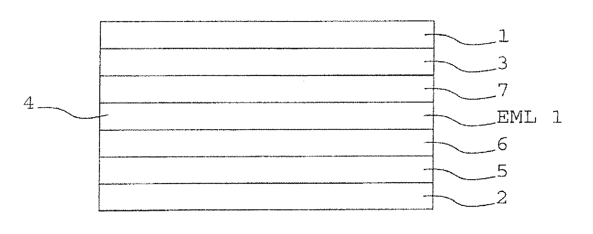
[0097]In the following, the invention is explained in more detail using exemplary embodiments with reference to figures of the drawing. They show:

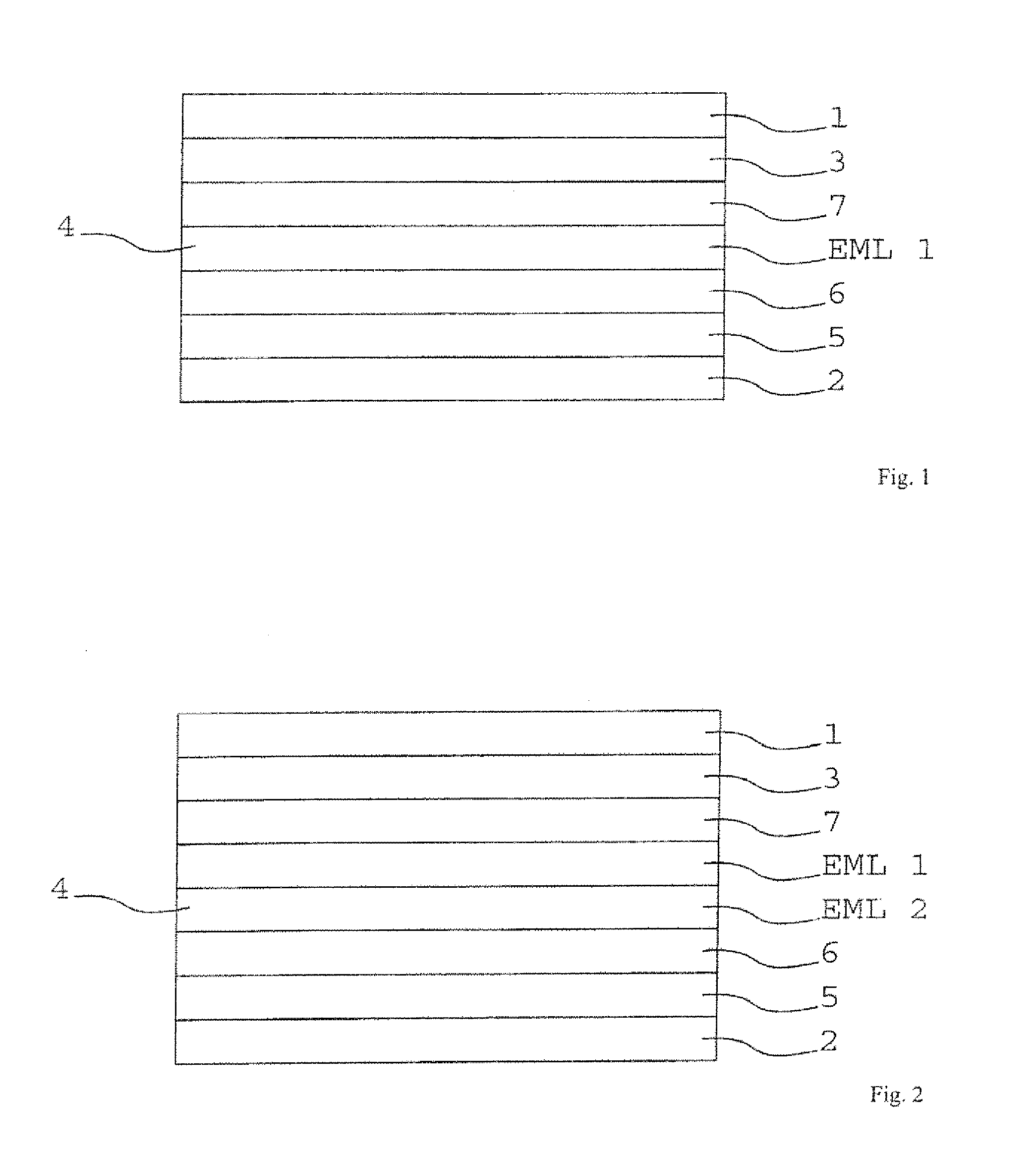
[0098]FIG. 1 a schematic illustration of an array of layers of an organic light-emitting component,

[0099]FIG. 2 a schematic illustration of an array of layers of a further organic light-emitting component,

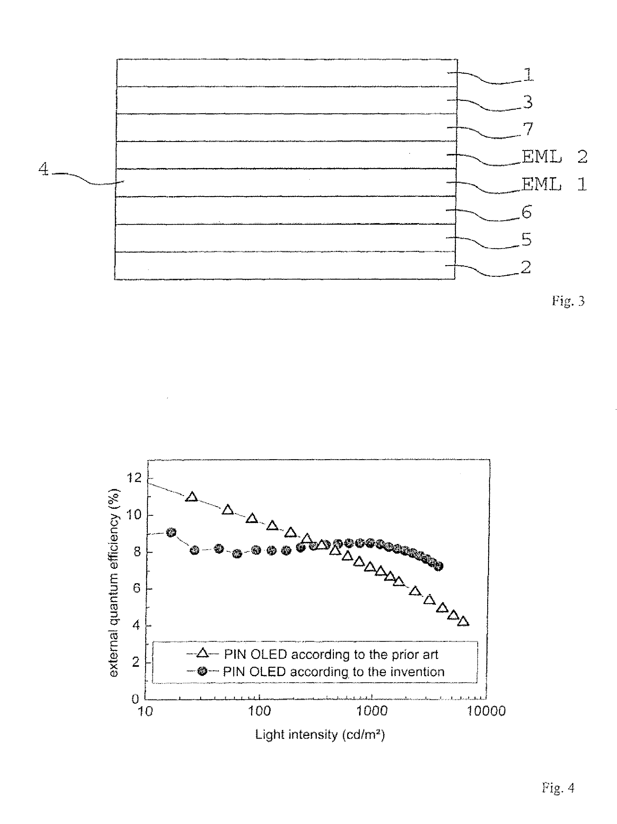
[0100]FIG. 3 a schematic illustration of an array of layers of a further organic light-emitting component,

[0101]FIG. 4 a graphic illustration of the quantum efficiency as a function of the light intensity of a reference luminescent diode according to the prior art and an organic luminescent diode according to the invention,

[0102]FIG. 5 a graphic illustration of an electroluminescence spectrum of the organic luminescent diode according to the invention,

[0103]FIG. 6 a graphic illustration of an electric field distribution of the light emission of an organic light-emitting component with several emission layers with different emission wavele...


PUM


Abstract

The invention relates to a light-emitting component, in particular an organic luminescent diode, having an electrode and a counter electrode and an organic region arranged between the electrode and the counter electrode and having an organic light-emitting region. Furthermore, the invention relates to methods for the production of such a component.

Description

[0001]The invention relates to technologies in the field of organic light-emitting components, in particular organic luminescent diodes.BACKGROUND OF THE INVENTION[0002]Organic luminescent diodes or organic light-emitting diodes (OLEDs) are by now generally seen as having the potential to offer an alternative to conventional lighting means such as incandescent lamps or fluorescent lamps within the field of lighting technology. By now, the achieved performance efficiencies (cf. for example D'Andrade et al., Adv. Mater. 16 (2004) 1585) are markedly higher than those of incandescent lamps. Current reports support the conclusion that the efficiencies of fluorescent lamps can also be surpassed. To achieve highest performance efficiencies, phosphorescent emitters are currently used as they are designed in such a way that they can convert 100% of the charge carriers employed into light, i.e. achieve a quantum efficiency of 100%.[0003]Besides the performance efficiency, the service life is ...

Claims


Application Information

Patent Timeline
Patent Type & Authority Applications(United States)
IPC IPC(8): H01L33/40
CPCH01L51/5016H01L2251/552H01L51/5036H10K50/125H10K50/11H10K2101/10H10K2101/30
Inventor REINEKE, SEBASTIANSCHWARTZ, GREGORLEO, KARLWALZER, KARSTEN
Owner NOVALED GMBH
Why Eureka
Try Eureka