Eureka AIR delivers breakthrough ideas for toughest innovation challenges, trusted by R&D personnel around the world.

Process for making ceramic insulation

a technology of ceramic insulation and process, applied in the field of ceramic insulation production methods, can solve the problems of limiting the diffusion (permeability) or molten metal of gas, pore size, glass or slag penetration, etc., and achieves the effect of low cost and superior performan

Inactive Publication Date: 2009-12-03
CERAMTEC
View PDF28 Cites 28 Cited by
  • Summary
  • Abstract
  • Description
  • Claims
  • Application Information

AI Technical Summary

Benefits of technology

[0015]The present invention is based on a reaction-bonded, high alumina material and offers low cost net-shape ceramic processing of insulation products with superior performance in harsh environments. The present invention is directed to processes, methods, and systems for the production of insulation components made of ceramic. This invention further teaches a new method to make phosphate-bonded alumina-based products at lower temperatures (15° C.-<100° C.) requiring significantly less phosphate-based reagents.
[0016]One of the methods to improve the insulative properties of the insulation is to decrease the pore size of the ceramic component. By reducing the pore size, the overall heat transfer ability is reduced, thus making it a better insulator. For a given porosity, a smaller pore size provides a greater number of particle-to-particle contact points which leads to greater strength. Further, a reduced pore size will also limit the gas diffusion (permeability) or molten metal, glass, or slag penetration into the surrounding ceramic insulating component. The reduced permeability or melt penetration will extend the lifetime of the component compared to a ceramic component with a coarser pore size (ten to hundreds of microns). One aspect of the present invention is to achieve a very fine pore size (pore size range from 1 nanometer to 10 micron with a majority less than 1 micron) in the ceramic insulation component. This may be accomplished by judiciously choosing the starting raw materials and particularly the ceramic powder size (between about 1 micron and 10 microns) and the slip formulation.
[0017]Another aspect of the present invention is to increase the strength-to-weight ratio of the ceramic component by maintaining a fine porosity, using a fine starting powder particle size, and by adding an appropriate amount of phosphate component as the bonding phase. For a given total pore volume, the finer the pore size, the greater the number of particle-to-particle contact points, which produce a higher flexural strength. By increasing the flexural strength, the erosion and wear resistance properties can be markedly improved and the time to failure of the ceramic component will be extended.
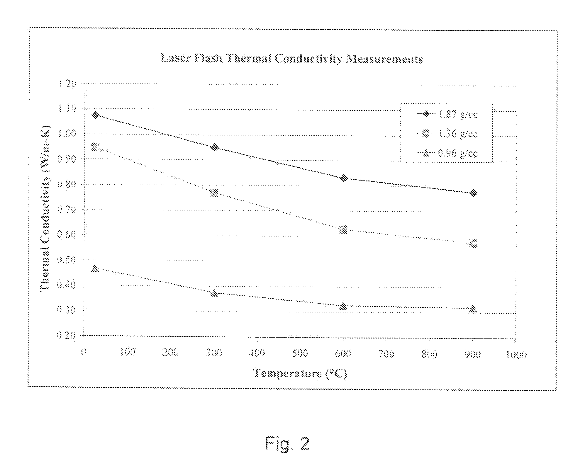
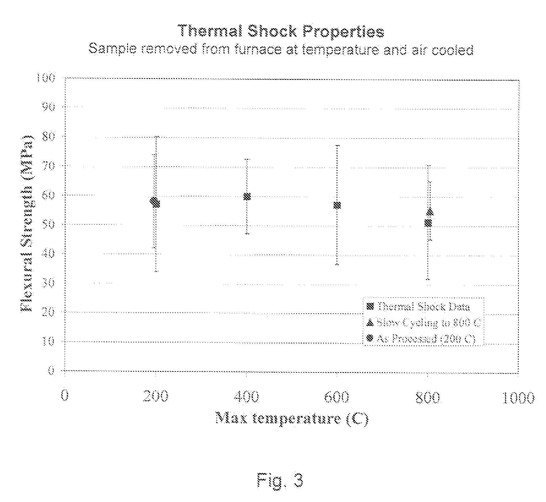
[0019]Ceramic components made using this technology may have several unique properties: (i) mechanical 4-point bend strength of <1-150 MPa (<145-21.750 psi)—three to five times stronger than what is currently available in the form of structural, ceramic oxide-based insulation (with comparable fired densities); (ii) excellent erosion and wear resistance (higher strength is generally correlated with higher wear- and erosion-resistance); (iii) high temperature capability (the maximum service temperature can be as high as 1650° C.); (iv) excellent hot modulus of rupture strength, i.e., it retains its mechanical strength at high temperatures); (iv) longer lifetime / improved corrosion and chemical resistance (the ultrafine nano-, meso-, and micro-porosity will limit gas diffusion and molten metal / glass / black liquor / slag penetration into the ceramic insulation); (v) good insulation and thermal shock properties (thermal conductivity can range from 0.2-5.0 W / m·K (7.0-35.0 BTU·in / hr·ft2·F—depending on the tired density)—its superior thermal shock resistance (along with nanoporosity and high strength) is expected to offer increased lifetime and superior performance in harsh environments; (vi) environmental and thermo-chemical stability (the material offers robust, stable performance in both oxidizing and reducing environments at high temperatures); (vii) Process flexibility & product availability: the material can be made available in various forms—castable mixes or powder pressed forms. This process flexibility allows the material to be available in a wide range of densities (0.6-3.5 g / cc, or, 37-217 lbs / cu. ft.) to suit the end user's needs—a lower density material, due to its lower thermal mass, can result in potential energy savings. On the other hand, the higher density version can be a good candidate for products where high strength or low permeability to gases is desired); (viii) design flexibility (functionally graded designs can be easily incorporated into the final products. For example, the porosity and chemical composition of the outer surface can be tailored to be different from that of inner bulk. Optionally, incorporating fibrous or particulate materials as mechanical reinforcements and infrared opacifants can also be achieved. Lastly, while the product is a high alumina (>95%), reaction bonded ceramic, it can have a second phase (<90 vol. %) in the form of mobile, zirconia, magnesia, iron oxide, chrome oxide, spinel, aluminum silicate, SiC, or if requested by the end user, silica-based too.
[0020]The material can be made available in a castable or a moldable form as a ceramic slip for conventional casting, or filter-pressing or as ceramic green feedstock for extrusion or injection molding. Thus the net-shaped and / or net-sized components can be formed in the green (pre-fired) stage. Such materials may provide low cost, one step processing, and under certain processing conditions may give net-shape or net-size components which will eliminate the need for post-machining processes. The proposed material system and method has also got a cost advantage over similar high alumina-based insulation available in the market.
[0024]Yet another aspect of the present invention is the ability to use significantly less phosphate-based reagents thereby reducing the financial and environmental costs associated with the manufacture of this product.

Problems solved by technology

Further, a reduced pore size will also limit the gas diffusion (permeability) or molten metal, glass, or slag penetration into the surrounding ceramic insulating component.

Method used


Image

  • Process for making ceramic insulation
  • Process for making ceramic insulation
  • Process for making ceramic insulation

Examples


example 1

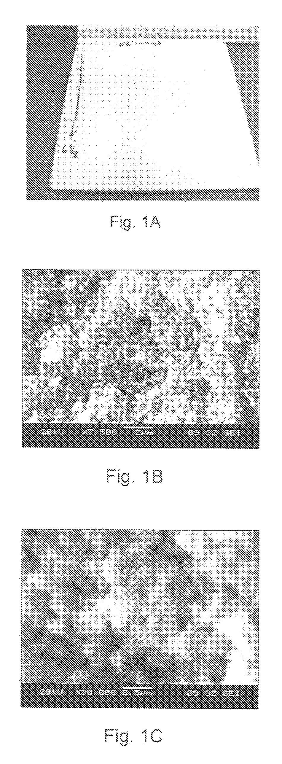
[0060]High purity (99.99%) alumina powder (with low surface area) having an average particle size of 2 μm was suspended in water using dispersants, binders, and plasticizers at 18 vol % solids. The suspension was paint-shaken with a small amount of alumina media to improve and speed up the dispersion process. A pore-former in the form of carbon was added at three different levels (i) 60 vol. %; (ii) 40 vol. %; and (iii) 0 vol %. Phosphoric acid was added to the mix to obtain the final slip. The resulting slurry was poured into the mold, dried and fired to 800° C. The resulting insulation material with 60 vol. % pore-former is illustrated in FIGS. 1A-1C. Table 1 below summarizes the sample properties.

TABLE IProperties for Sample with 60 vol. % pore-formerValueDensity (g / cc)0.80g / ccFlexural Strength (MPa)MPaThermal Conductivity (W / m · K) at 800° C.0.3W / m · K

This technique allows for incorporating very fine porosity (≦1 micron) into the ceramic matrix thus making it a very effective in...

example 2

[0061]High purity alumina powder with an average particle size of 5 μm was suspended in water using dispersants, binders, and plasiticizers at 45 vol. % solids. Dispersants, binders, and plasticizers were added in the range of 9.0 wt. % to obtain a fully dispersed slurry with low viscosity (<1000 cP). Phosphoric acid was added and the slurry was intimately mixed at room temperature using a mixer. No external heating was applied during the mixing process. While mixing the slurry with the acid, a modest temperature increase was observed as a result of the mixing process. The ratio of the weight of acid to total weight of all alumina-based solids was less than 1.0. The slurry was then poured into a desired mold and allowed to dry in an oven at 40° C. The drying temperature can range from room temperature to 100° C. but preferably between 22° C.-70° C. The green component, after drying, was fired at a temperature of about 900° C. for 12 hours.

[0062]Table II below outlines the strength a...

example 3

[0063]A slip is made according to the procedure of Example 2. A portion of the 100% alumina slip is poured into the mold and left to dry. A quantity of silicon carbide powders is added to the leftover portion of the alumina slip in an amount of about 50 vol. %. This second alumina-silicon carbide (50 / 50) (by volume) slip is then poured on top of the first alumina cast sample and left to dry. A schematic of the multilayered final product 20 using this technique is shown in FIG. 4. The multilayered product 20 has two layers—bottom layer 22 is 100% alumina, while the top layer 24 is a 50 / 50 mixture of alumina and silicon carbide. It will be appreciated that this technique may be used to prepare multilayered insulation having a variety of different compositions and properties.


PUM

PropertyMeasurementUnit
mean particle sizeaaaaaaaaaa
temperatureaaaaaaaaaa

Abstract

A method is provided for producing insulation materials and insulation for high temperature applications using novel castable and powder-based ceramics. The ceramic components produced using the proposed process offers (i) a fine porosity (from nano-to micro scale); (ii) a superior strength-to-weight ratio; and (iii) flexibility in designing multilayered features offering multifunctionality which will increase the service lifetime of insulation and refractory components used in the solid oxide fuel cell, direct carbon fuel cell, furnace, metal melting, glass, chemical, paper / pulp, automobile, industrial heating, coal, and power generation industries. Further, the ceramic components made using this method may have net-shape and / or net-size advantages with minimum post machining requirements.

Description

CROSS-REFERENCE TO RELATED APPLICATION[0001]This application claims the benefit of U.S. Provisional Application No. 60 / 729,128 filed Oct. 21, 2005 and incorporated herein by reference.STATEMENT REGARDING FEDERALLY SPONSORED RESEARCH[0002]This invention was made in part with government support under Contract No.: DE-FG02-03ER83619 awarded by the Department of Energy and Contract / Award No. DMI-0321692, awarded by the National Science Foundation. The Government has certain rights in the inventions.BACKGROUND OF THE INVENTION[0003]The present invention relates in general to methods for producing ceramic insulation by introducing very small-sized porosity in the fired ceramic in a controlled fashion, and production of multilayered, multifunctional ceramic components. Further, the present invention includes methods to produce net-shape and / or net-size ceramic insulation components. The present invention would be applicable for high temperature applications as insulation or refractory comp...

Claims


Application Information

Patent Timeline
Patent Type & Authority Applications(United States)
IPC IPC(8): C04B35/64C04B35/00
CPCB32B18/00Y02E60/525C04B35/447C04B35/565C04B35/6263C04B35/62805C04B35/803C04B38/0645C04B41/009C04B41/5031C04B41/87C04B2111/00793C04B2111/0081C04B2111/00853C04B2235/3217C04B2235/3826C04B2235/402C04B2235/5224C04B2235/5409C04B2235/5436C04B2235/6027C04B2235/656C04B2235/77C04B2235/96C04B2235/9607C04B2237/343C04B2237/365C04B2237/58C04B2237/584C04B2237/586H01M8/0282H01M8/1233H01M2008/1293Y02E60/50C04B35/117C04B35/10C04B38/08C04B35/80C04B41/4539C04B41/4582C04B35/00C04B38/00Y02P70/50
Inventor AKASH, AKASHBALAKRISHNAN G., NAIR
Owner CERAMTEC
Why Eureka
Eureka Blog
Learn More