Supporting and locking device and supporting equipment of cantilever type lifting stage

A technology of locking device and supporting equipment, which is applied in the field of stage machinery, can solve problems such as sudden drop of stage body, small space, heavy mechanism weight, etc., to eliminate the possibility of overturning, apply to a wide range of sites, and improve work safety Effect

Pending Publication Date: 2022-01-14
北京秀域科技文化股份有限公司
View PDF0 Cites 0 Cited by
  • Summary
  • Abstract
  • Description
  • Claims
  • Application Information

AI Technical Summary

Problems solved by technology

The use of this pin locking structure has the following problems: a. The positioning of the lifting table body is highly demanding, otherwise the pins cannot be inserted into the corresponding locking holes; The stage guiding device produces extra force, which is easy to cause equipment damage; c. When the pin is pulled out, the resistance is large, and the pin is often difficult to pull out; d. The mechanism using the pin locking is heavy and expensive; e. The locking platform The pin behind the body is subjected to a large shear force, and there will be a danger of the table body suddenly falling due to the breakage of the pin, which will affect the safety of the equipment and bring risks to the personal safety of the entertainers
[0005] However, the places where performances can be watched are no longer limited to traditional large theaters, but also in other theaters, such as theaters built with the development of tourism. Usually these theaters are rebuilt or redesigned from some traditional stages. Small-scale stages with shallow foundation pits or stages with limited space. The civil engineering conditions of these stages are not ideal, and the space is too small to set guide rails on both sides of the support structure. In this case, it is suitable for large-scale theaters. Elevator-type guides with separate guide rails on both sides are no longer suitable

Method used


Image

  • Supporting and locking device and supporting equipment of cantilever type lifting stage
  • Supporting and locking device and supporting equipment of cantilever type lifting stage
  • Supporting and locking device and supporting equipment of cantilever type lifting stage

Examples


Embodiment Construction

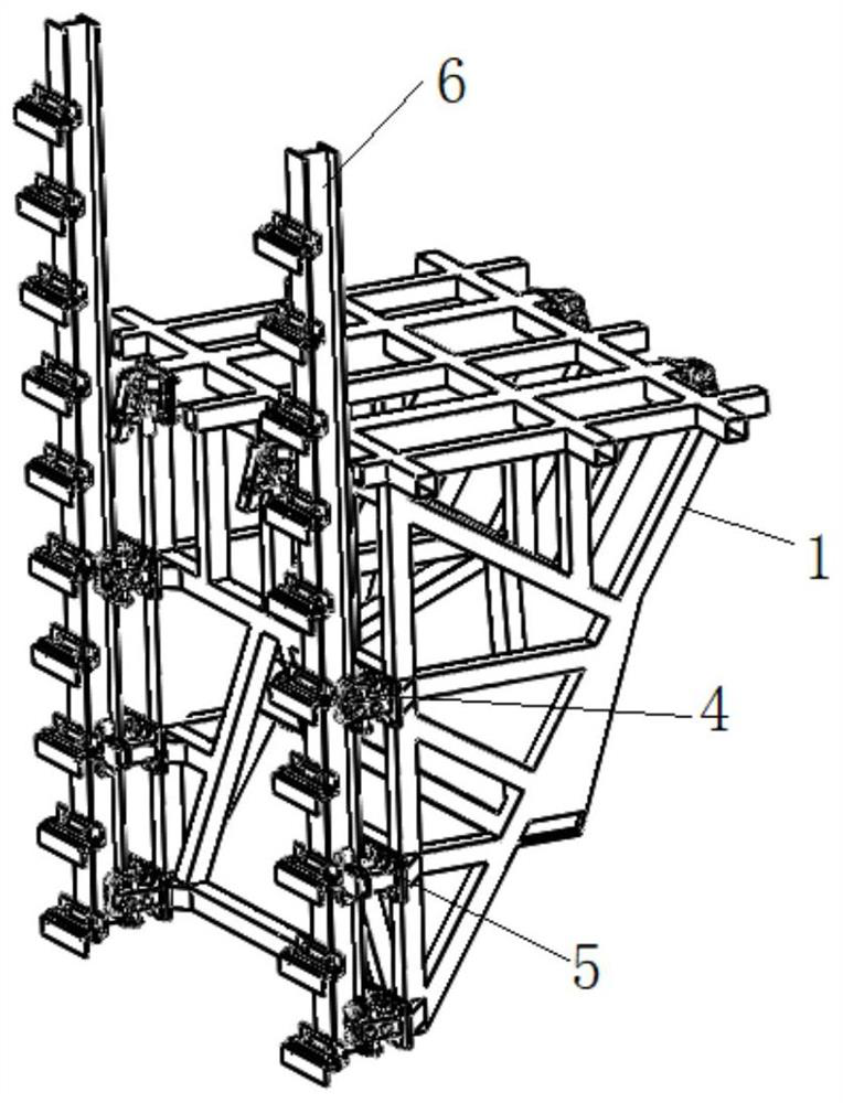
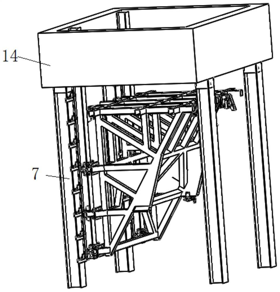
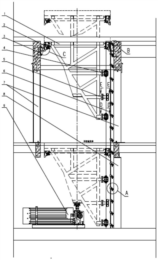
[0082] Such as Figure 1a As shown, it is a partial perspective view of a cantilever lifting stage with a structural support locking device of the present invention, as Figure 1b Shown is a perspective view of the upper part of the structure of the upper steel column of the lifting stage, as shown in Figure 2a, Figure 2b Shown are respectively the front view and the left view of the cantilever lifting stage with the support locking device of the present invention, as image 3 As shown, it is a structural schematic diagram of another structural support locking device of the present invention, as Figure 4 - Figure 8 respectively Figure 2a , Figure 2b Enlarged view of parts A-E in .

[0083] Among them, the support locking device of the cantilever lifting stage of the present invention includes: multiple pairs of movable outrigger mechanisms installed around the body of the cantilever lifting stage; multiple pairs of support seats installed around the building structure...


PUM


Abstract

The invention discloses a supporting and locking device and supporting equipment of a cantilever type lifting stage. The supporting and locking device comprises a plurality of pairs of movable supporting leg mechanisms installed around a cantilever type lifting stage body and a plurality of pairs of supporting bases installed around a building structure, or comprises a plurality of pairs of movable supporting leg mechanisms installed around a building structure used for containing the cantilever type lifting stage and a plurality of pairs of supporting bases installed around the cantilever type lifting stage body. The movable supporting leg mechanisms and the supporting bases are used in a paired mode, and supporting legs of the movable supporting leg mechanisms can rotate relative to the stage body or the building structure and stretch out or out of the stage body so as to abut against the corresponding supporting bases and lock the stage body. The supporting and locking device is small in occupied space, capable of being used for performance sites with limited space, high in bearing capacity, convenient to install and maintain, easy to manufacture and low in cost.

Description

technical field [0001] The invention relates to the technical field of stage machinery, in particular to a support locking device and support equipment for a cantilever lifting stage. Background technique [0002] In the past ten years, with the people's cultural life becoming more and more abundant, the demand and products for the performance market have become more and more diversified. In order to improve the stage effect, theaters usually use a liftable stage to present a lively three-dimensional performance effect. [0003] In the existing liftable stage, the auxiliary support of the lifting platform body is in the form of pin insertion and extraction. When the lifting platform body stops, the pins on the lifting platform body extend horizontally and are inserted into the locking holes of the guide device to lock the platform body. The use of this pin locking structure has the following problems: a. The positioning of the lifting table body is highly demanding, otherwis...

Claims


Application Information

Patent Timeline
IPC IPC(8): E04H3/26E04H3/24
CPCE04H3/26E04H3/24
Inventor 魏琦吕圣龙卢金珠
Owner 北京秀域科技文化股份有限公司
Why Eureka
Try Eureka