Damping device used for forging

A technology of shock absorber and shock absorber, which is applied in the direction of shock absorber, spring/shock absorber, shock absorber, etc. It can solve the problems of spring knotting, affecting the normal use of forging equipment, and entanglement, so as to improve Shock absorption efficiency, avoid vibration disturbance, improve the effect of shock absorption effect

Pending Publication Date: 2017-08-25
四川瑞丰锻造有限公司
View PDF10 Cites 2 Cited by
  • Summary
  • Abstract
  • Description
  • Claims
  • Application Information

AI Technical Summary

Problems solved by technology

The shock absorbing structure is damped by a spring arranged between the upper pillar and the lower pillar. Although the purpose of shock absorption can be achieved through the spring, but limited by the shock absorption requirements, if the spring between the upper pillar and the lower pillar When there are many and dense springs, it is easy to cause the adjacent springs to become knotted and entangled in the process of recovering deformation, which will affect the normal use of the forging equipment.

Method used


Image

  • Damping device used for forging
  • Damping device used for forging
  • Damping device used for forging

Examples


Embodiment 1

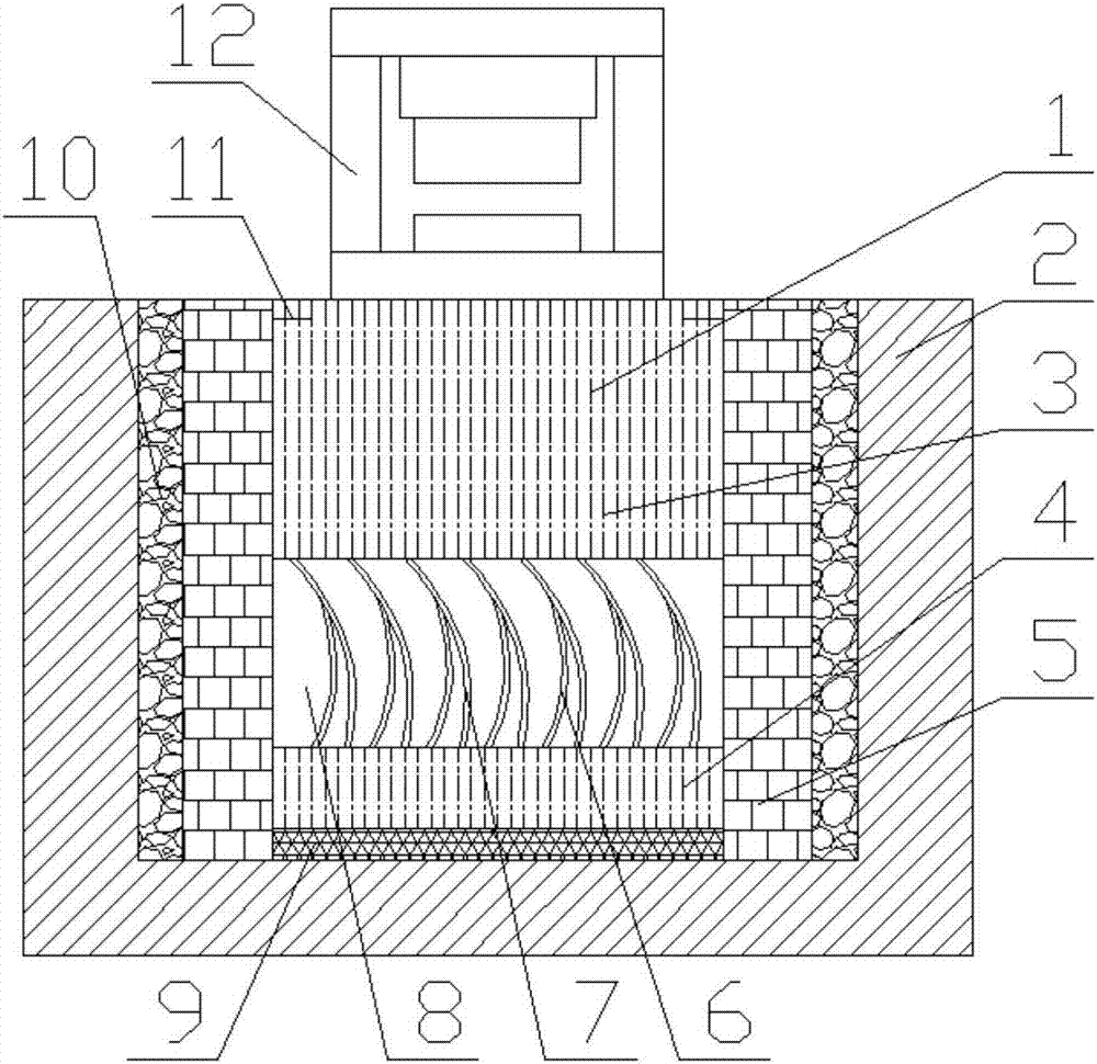
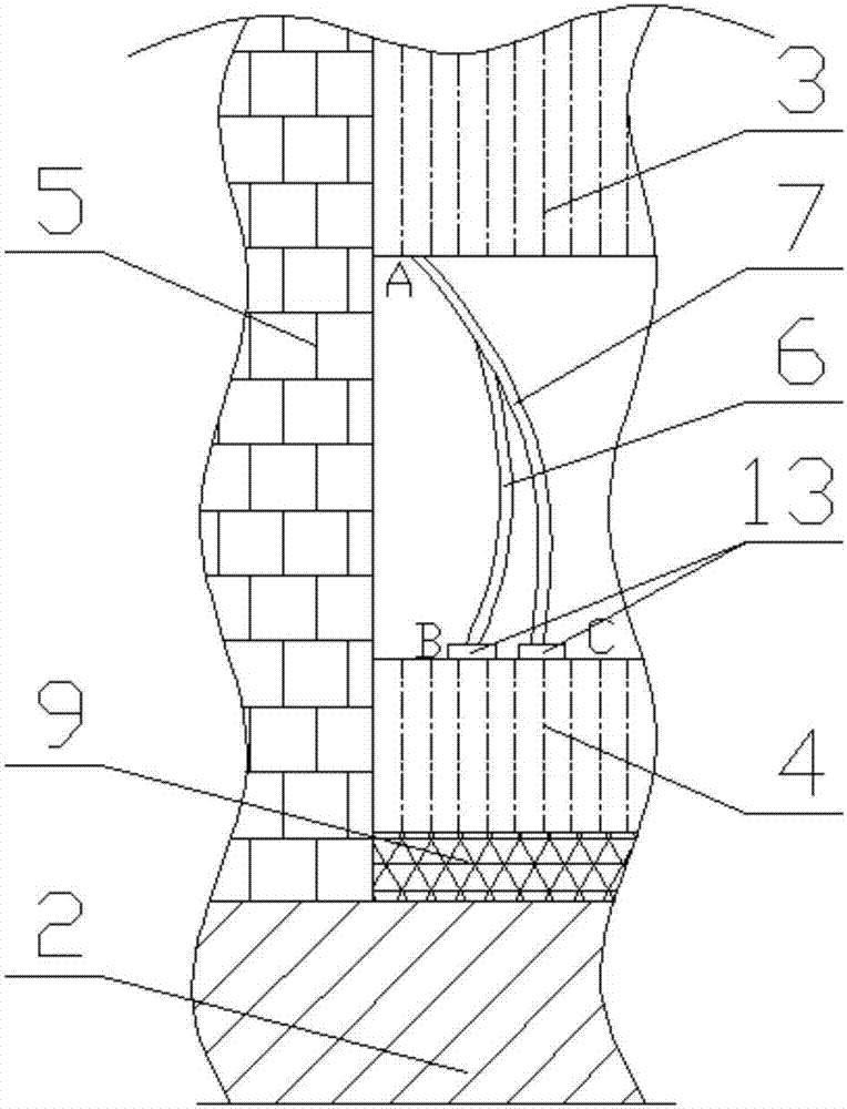
[0031] A shock absorbing device for forging, comprising a groove 1 dug on the ground, a concrete layer 2 is provided around the groove 1 and the bottom surface, an upper pillar 3 and a lower pillar 4 are arranged at the center of the groove 1, Around the upper pillar 3 and the lower pillar 4, an enclosure wall 5 is provided, the enclosure wall 5 can adopt a brick wall structure, and a hard rubber pad 9 is placed under the lower pillar 4, and the forging equipment 12 is fixed on the upper pillar 3; A sandstone layer 10 is filled between the outer layer and the side wall of the groove 1 . Multiple sets of damping structures are arranged between the upper pillar 3 and the lower pillar 4, and multiple sets of shock absorbing devices are evenly distributed along the cross-sectional direction of the groove 1 to achieve this. The damping structure includes a main damping plate 7, the two ends of the main damping plate 7 are respectively connected with the upper pillar 3 and the lower...

Embodiment 2

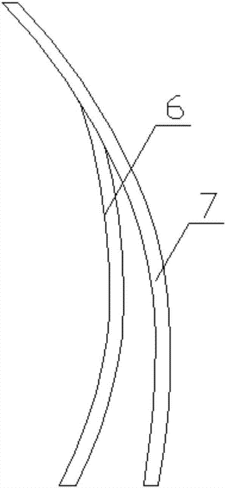
[0033] On the basis of Embodiment 1, the main shock absorbing plate 7 is set as an arc-shaped main shock absorbing plate 7, the secondary shock absorbing plate 6 is set as an arc-shaped secondary shock absorbing plate 6, and the protrusion direction of the main shock absorbing plate 7 Consistent with the protruding direction of the auxiliary shock absorbing plate 6, the main shock absorbing plate 7 is connected with the auxiliary shock absorbing plate 6 to form a herringbone structure.

Embodiment 3

[0035] On the basis of Embodiment 1, the main shock absorbing plate 7 is set as an arc-shaped main shock absorbing plate 7, the secondary shock absorbing plate 6 is set as an arc-shaped secondary shock absorbing plate 6, and the protrusion direction of the main shock absorbing plate 7 Contrary to the protruding direction of the auxiliary shock absorbing plate 6, the main shock absorbing plate 7 is connected with the auxiliary shock absorbing plate 6 to form a herringbone structure.


PUM


Abstract

The invention discloses a damping device used for forging and belongs to the technical field of forging and pressing equipment. According to the provided damping device used for forging, different damping structures are adopted, and normal use of the damping device is ensured. The damping device comprises a groove excavated in the ground. A concrete layer is arranged on the periphery and the bottom surface of the groove. A hard rubber pad, a lower supporting column and an upper supporting column are sequentially arranged in the groove from bottom to top. An enclosing wall is arranged on the peripheries of the outer sides of the upper supporting column and the lower supporting column. A gravel layer is filled between the outer layer of the enclosing wall and the side wall of the groove. The multiple sets of damping structures are arranged between the upper supporting column and the lower supporting column. Each damping structure comprises a main damping plate. The two ends of each main damping plate are connected with the upper supporting column and the lower supporting column correspondingly. An auxiliary damping plate is further connected to each main damping plate. The other end of each auxiliary damping plate is connected with the upper supporting column or the lower supporting column. The damping device used for forging is suitable for forging equipment.

Description

technical field [0001] The invention belongs to the technical field of forging equipment, and relates to a damping device for forging equipment. Background technique [0002] Forging is a processing method that uses forging machinery to apply pressure to metal blanks to cause plastic deformation to obtain forgings with certain mechanical properties, certain shapes and sizes. It is one of the two major components of forging (forging and stamping). Forging can eliminate defects such as as-cast porosity produced in the metal smelting process and optimize the microstructure. At the same time, due to the preservation of complete metal flow lines, the mechanical properties of forgings are generally better than castings of the same material. For important parts with high loads and severe working conditions in related machinery, forgings are mostly used, except for plates, profiles or weldments that can be rolled with simpler shapes. [0003] In the prior art, since forging utilize...

Claims


Application Information

Patent Timeline
IPC IPC(8): F16F7/00
CPCF16F7/00F16F2230/0047F16F2230/08F16F2230/24
Inventor 黄韬
Owner 四川瑞丰锻造有限公司
Why Eureka
Try Eureka