Novel power equipment convenient to move

A technology for power equipment and easy movement, which is applied to anti-seismic equipment, electrical components, substation/power distribution device shells, etc. It can solve problems such as shortening service life, affecting normal heat dissipation of power equipment, and inconvenient movement, so as to reduce noise generation , Conducive to normal movement, avoid vibration disturbing effect

Inactive Publication Date: 2018-11-16
郭秀云
View PDF12 Cites 4 Cited by
  • Summary
  • Abstract
  • Description
  • Claims
  • Application Information

AI Technical Summary

Problems solved by technology

[0002] During the construction process of the construction site, a lot of power equipment needs to be used, so the power equipment needs to be used, but now many power distribution equipment are very inconvenient to move, which makes it very inconvenient to change the location of the power equipment. , it is also necessary to disassemble the entire power equipment, which seriously wastes a lot of human resources and increases cost consumption. Moreover, when installing power equipment, especially higher power equipment, many birds will land or nest on the top of the power equipment. As a result, the power equipment cannot operate normally, and because the power equipment is installed relatively high, the top surface of the power equipment cannot be cleaned well, resulting in a backlog of dust, which affects the normal heat dissipation of the entire power equipment, and because the power equipment will vibrate when it is working, if Install the power equipment directly on the distribution box or the equipment rack. The vibration generated by the power equipment will hit the distribution box or the equipment rack to generate noise. At the same time, the vibration generated by the power equipment will hit the distribution box or the equipment rack, which will also affect The normal operation of electrical equipment can easily lead to damage to electrical equipment and shorten its service life

Method used


Image

  • Novel power equipment convenient to move
  • Novel power equipment convenient to move
  • Novel power equipment convenient to move

Examples


Embodiment Construction

[0025] Below in conjunction with accompanying drawing and specific embodiment the present invention is described in further detail:

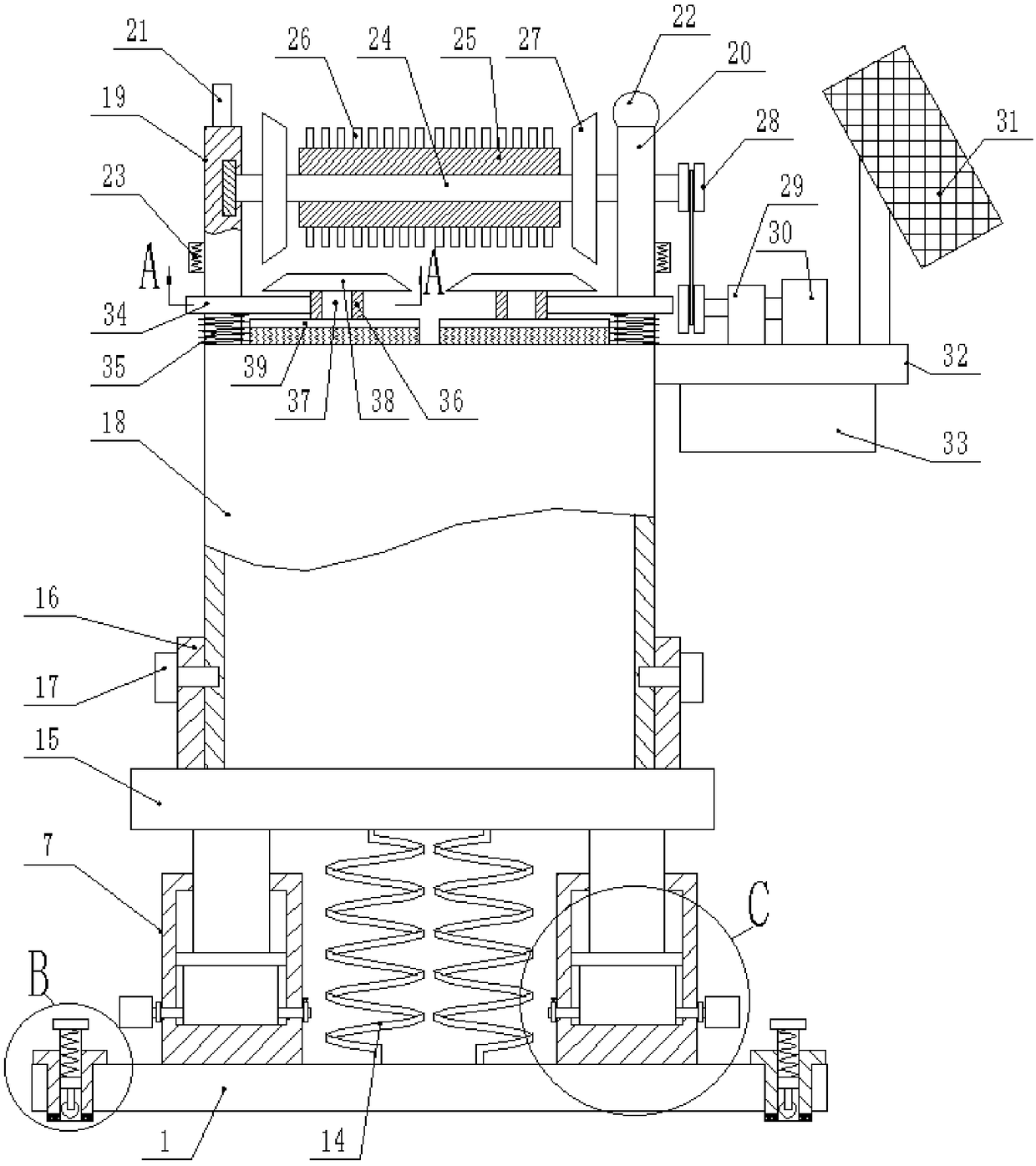
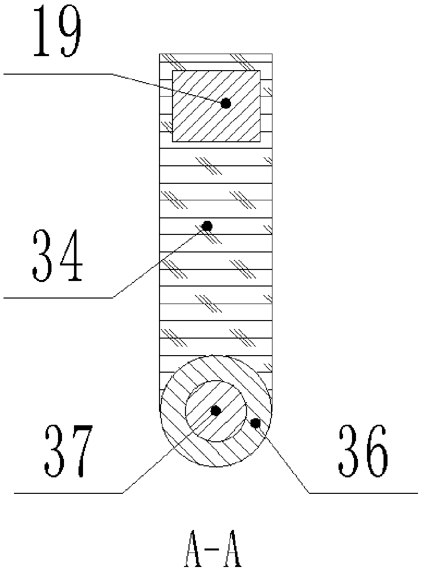
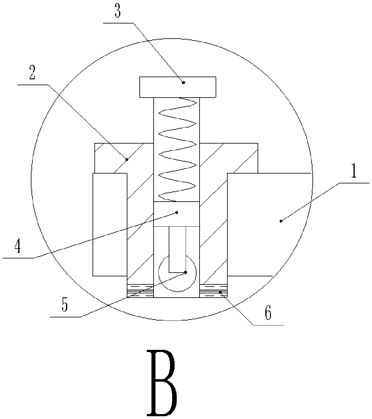
[0026] Such as figure 1 , figure 2 , image 3 , Figure 4 , Figure 5 As shown, a new type of power equipment that is convenient to move includes a base 1, a T-shaped sleeve 2 is fixedly embedded in the four corners of the base 1, and a non-slip support pad 6 is fixedly attached to the bottom of the T-shaped sleeve 2. Bolts 3 are screwed inside the T-shaped sleeve 2, the bottom ends of the bolts 3 are fixedly connected with the connection block 4, the bottom end of the connection block 4 is fixedly connected with a universal wheel 5, and the top end of the base 1 is fixedly connected with multiple Barrel 7, a plurality of damping springs 14 are arranged between the two barrels 7, the inside of the barrel 7 is slidably connected with a limit slider 9, and the top of the limit slider 9 is fixedly connected with a sliding support rod 8, The t...


PUM


Abstract

The invention discloses novel power equipment convenient to move, which comprises a base, wherein T-shaped sleeves are fixedly embedded at four corners of the base, the bottom end of each T-shaped sleeve is fixedly adhered with an anti-slip supporting pad, each T-shaped sleeve is internally connected with a bolt in a threaded manner, the bottom end of each bolt is fixedly connected with a connecting block, the bottom end of the connecting block is fixedly connected with a universal wheel, the top end of the base is fixedly connected with a plurality of barrel bodies, a plurality of damping springs are arranged between two barrel bodies, and a limiting slide block is in sliding connection with the interior of each barrel body. The novel power equipment is convenient to move or install, is very convenient to use, effectively achieves the bird repellent effect since birds cannot stand on rollers stably, reduces the operating difficulty for the operator, is convenient for people to use, and adopts a PLC controller to control electromagnets, so that a motor can drive a cleaning brush, and dust on the top surface of the power equipment can be cleaned regularly, thereby ensuring the normal operation of the power equipment, having better shock absorption effect, and being conductive to the normal movement of the power equipment.

Description

technical field [0001] The invention relates to the field of electric equipment, in particular to a novel electric equipment which is convenient to move. Background technique [0002] During the construction process of the construction site, a lot of power equipment needs to be used, so it is necessary to use power equipment, but now a lot of power equipment for power distribution is very inconvenient to move, which makes it very inconvenient to change the location of power equipment. , it is also necessary to disassemble the entire power equipment, which seriously wastes a lot of human resources and increases cost consumption. Moreover, when installing power equipment, especially higher power equipment, many birds will land or nest on the top of the power equipment. As a result, the power equipment cannot operate normally, and because the power equipment is installed relatively high, the top surface of the power equipment cannot be cleaned well, resulting in a backlog of du...

Claims


Application Information

Patent Timeline
Patent Type & Authority Applications(China)
IPC IPC(8): H02B1/30H02B1/54
CPCH02B1/303H02B1/54
Inventor 张明明
Owner 郭秀云
Why Eureka
Try Eureka