Forging equipment

A kind of equipment and forging technology, which is applied in the direction of metal processing equipment, forging presses, forging presses, etc., can solve problems such as connection defects between briquetting blocks and hydraulic rods, briquetting blocks falling off, and briquetting blocks tilting, so as to avoid vibration disturbance and improve shock absorption Efficiency, the effect of avoiding damage

Inactive Publication Date: 2017-08-11
四川瑞丰锻造有限公司
View PDF7 Cites 2 Cited by
  • Summary
  • Abstract
  • Description
  • Claims
  • Application Information

AI Technical Summary

Problems solved by technology

When the thickness of the workpiece is different or the strength of the two sides is different, the method of applying pressure in the middle will easily cause the pressure block to gradually tilt, and finally cause defects in the connection between the pressure block and the hydraulic rod, and the pressure block will fall from the hydraulic shaft during the forging process. fall off, and it is very easy to cause a safety accident

Method used


Image

  • Forging equipment
  • Forging equipment
  • Forging equipment

Examples


Embodiment 1

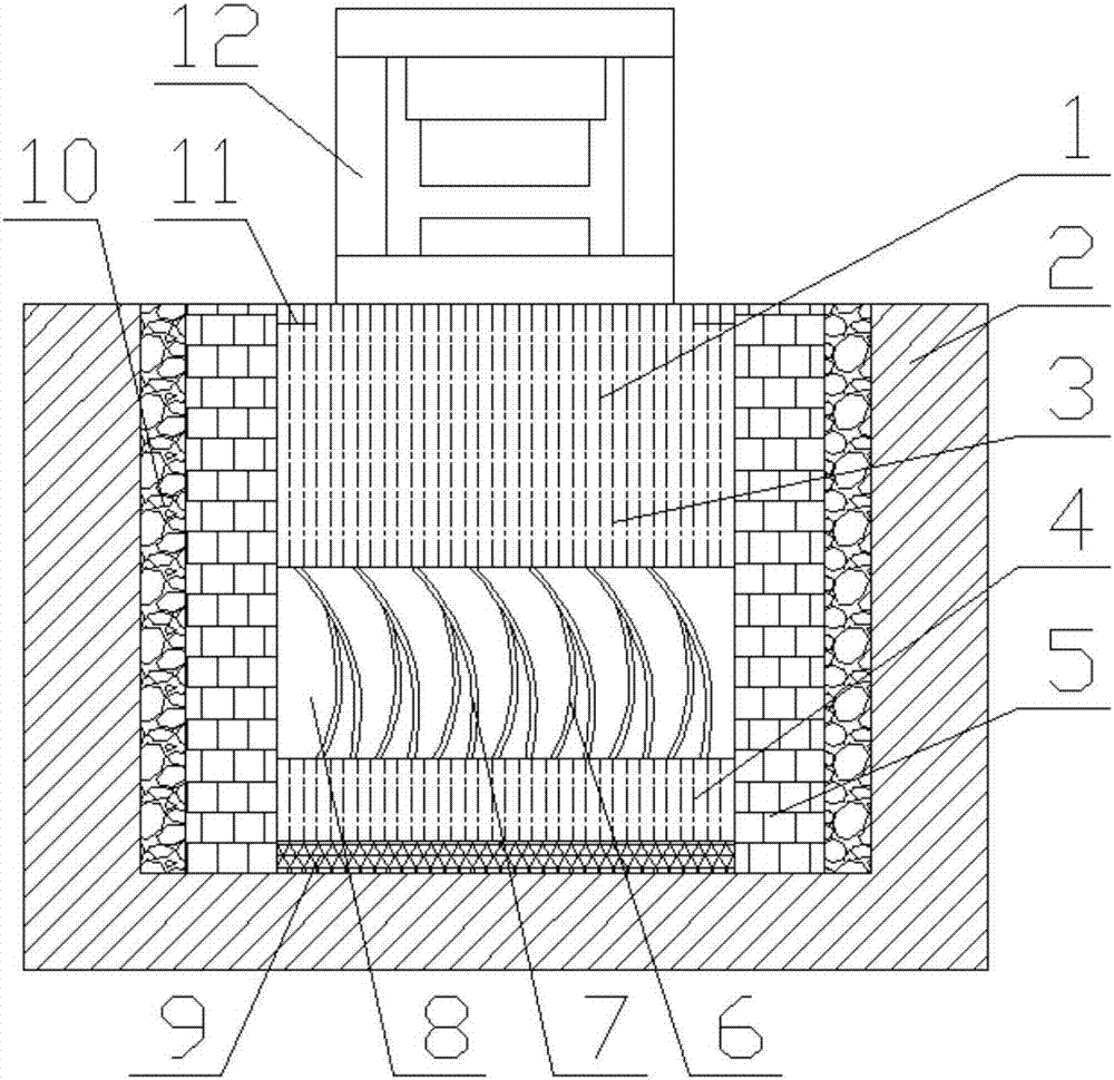
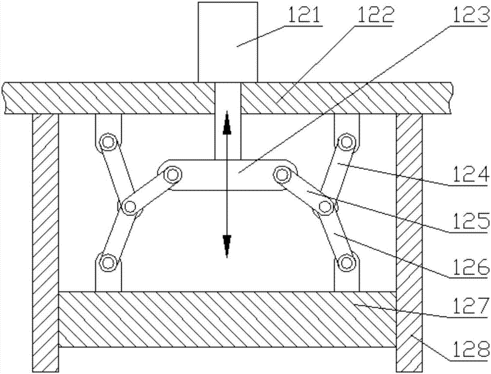
[0034] A shock-absorbing device for forging, comprising a groove 1 excavated in the ground, a concrete layer 2 is arranged around and on the bottom of the groove 1, and an upper pillar 3 and a lower pillar 4 are arranged in the center of the groove 1. Surrounding the upper pillar 3 and the lower pillar 4 is provided with an enclosure 5, the enclosure 5 can be a brick wall structure, under the lower pillar 4 is padded with a hard rubber pad 9, the forging equipment 12 is fixed on the upper pillar 3; A sandstone layer 10 is filled between the outer layer and the side wall of the groove 1. Multiple sets of shock-absorbing structures are arranged between the upper pillar 3 and the lower pillar 4, and the multiple sets of shock-absorbing devices are uniformly distributed along the cross-sectional direction of the groove 1, which is realized. The forging device 12 includes a frame 122, a hydraulic cylinder 121 arranged on the frame 122, and guide rails 128 arranged on both sides of t...

Embodiment 2

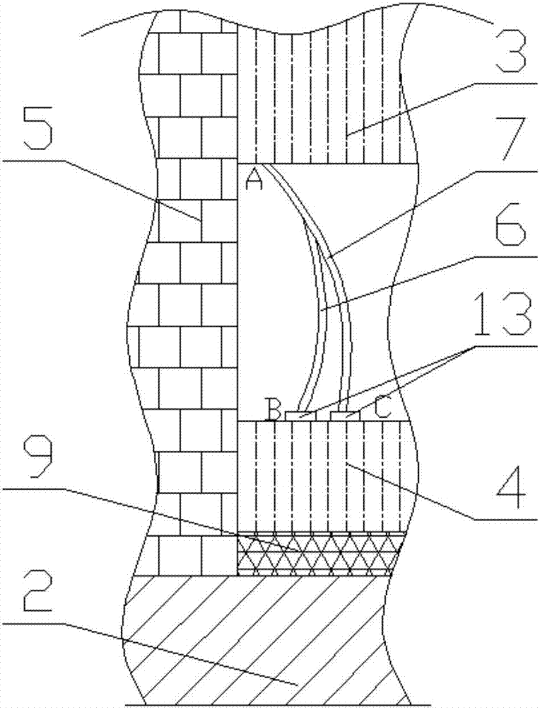
[0036] On the basis of the first embodiment, the damping structure includes a main damping plate 7. The two ends of the main damping plate 7 are respectively connected with the upper pillar 3 and the lower column 4, and the main damping plate 7 is also connected with auxiliary damping The other end of the plate 6 and the auxiliary damping plate 6 is connected with the upper pillar 3 or the lower pillar 4. When the forging equipment 12 exerts downward force, the main damping plate 7 and the auxiliary damping plate 6 will be squeezed, and the main damping plate 7 and the auxiliary damping plate 6 will be deformed, thereby achieving the purpose of damping and buffering.

Embodiment 3

[0038] On the basis of the second embodiment, the main damping plate 7 is set as an arc-shaped main damping plate 7, the auxiliary damping plate 6 is set as an arc-shaped auxiliary damping plate 6, and the convex direction of the main damping plate 7 Consistent with the convex direction of the auxiliary damping plate 6, the main damping plate 7 and the auxiliary damping plate 6 are connected to form a herringbone structure.


PUM


Abstract

The invention discloses a forging equipment, which belongs to the technical field of forging equipment, and aims to provide a forging equipment with uniform force at both ends, so as to prolong the service life of the forging equipment. It includes a forging device, a groove, a concrete layer is provided around the groove and the bottom surface, a hard rubber pad, a lower pillar and an upper pillar are arranged in the groove, and a shock-absorbing structure is arranged between the upper pillar and the lower pillar. There is a wall around the outer side of the upper pillar and the lower pillar, the forging device is installed on the upper pillar, and a layer of sand is filled between the outer layer of the wall and the side wall of the groove; the forging device includes a frame, a hydraulic cylinder, and a guide rail. There is a pressure block between the two guide rails, a connecting block is connected to the end of the hydraulic shaft, and a connecting rod mechanism is symmetrically arranged on the left and right sides of the hydraulic shaft. The middle parts of the three connecting rods of the connecting rod mechanism are hinged together. The parts are respectively hinged on the frame, hinged on the connection block, and hinged on the pressing block. The invention is suitable for forging equipment.

Description

Technical field [0001] The invention belongs to the technical field of forging equipment and relates to a forging equipment. Background technique [0002] Forging is a processing method that uses forging machinery to apply pressure to metal blanks to produce plastic deformation to obtain forgings with certain mechanical properties, certain shapes and sizes. It is one of the two major components of forging (forging and stamping). Forging can eliminate defects such as as-cast looseness during metal smelting and optimize the microstructure. At the same time, due to the preservation of complete metal flow lines, the mechanical properties of forgings are generally better than those of castings of the same material. For the important parts of related machinery with high load and severe working conditions, forgings are mostly used except for simpler shapes that can be rolled, profiles or welded parts. [0003] In the prior art, since forging uses pressure on the metal blank to deform the...

Claims


Application Information

Patent Timeline
Patent Type & Authority Applications(China)
IPC IPC(8): B21J9/02B21J9/18F16F15/02
CPCB21J9/02B21J9/18F16F15/02
Inventor 黄韬
Owner 四川瑞丰锻造有限公司
Why Eureka
Try Eureka