Ejector pin system

A technology of thimble and thimble hole, applied in the field of thimble system, to achieve the effect of sufficient vacuum, quick and easy replacement of thimble, and ensure the vacuum adsorption force

Inactive Publication Date: 2017-08-25
大连佳峰自动化股份有限公司
View PDF3 Cites 4 Cited by
  • Summary
  • Abstract
  • Description
  • Claims
  • Application Information

AI Technical Summary

Problems solved by technology

[0006] The purpose of the present invention is to provide a thimble system to solve the above-mentioned problems in the prior art, which solves the demoulding problem of large chips, is suitable for chips of various sizes, and the replacement of thimbles is fast, simple and convenient

Method used


Image

  • Ejector pin system
  • Ejector pin system
  • Ejector pin system

Examples


Embodiment Construction

[0027] The following will clearly and completely describe the technical solutions in the embodiments of the present invention with reference to the accompanying drawings in the embodiments of the present invention. Obviously, the described embodiments are only some, not all, embodiments of the present invention. Based on the embodiments of the present invention, all other embodiments obtained by persons of ordinary skill in the art without making creative efforts belong to the protection scope of the present invention.

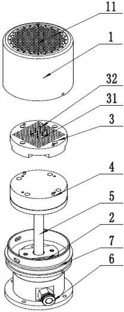
[0028] The purpose of the present invention is to provide a thimble system to solve the problems existing in the prior art, which solves the demoulding problem of large chips well, is suitable for chips of various sizes, and the replacement of thimbles is fast, simple and convenient.

[0029] In order to make the above objects, features and advantages of the present invention more comprehensible, the present invention will be further described in detail below i...


PUM


Abstract

The invention discloses an ejector pin system, which comprises an ejector pin cap and a guide base, and is characterized in that the upper end face of the ejector pin cap is provided with first ejector pin holes, and the bottom of the ejector pin cap is connected with the guide base; the upper end of the guide base is further connected to an ejector pin fixing device, the ejector pin fixing device is located in the ejector pin cap, the upper surface of the ejector pin fixing device is provided with second ejector pin holes which are used for fixing ejector pins; the ejector pin fixing device comprises an ejector pin base and a magnetic attraction base, the magnetic attraction base is located at the bottom of the ejector pin base, fixation of the ejector pins adopts of a mode of magnetic attraction, and replacement is performed quickly, simply and conveniently; and both the first ejector pin holes and the second ejector pin hole adopt array distribution, any number of ejector pins can be installed at any positions, thereby being applicable to various sizes of chips, and being easy to demould the chips.

Description

technical field [0001] The invention relates to the technical field of chip stripping, in particular to a thimble system. Background technique [0002] The thimble system is an indispensable mechanism in the chip back-end packaging, which is used to separate the chip on the wafer from the film. [0003] The traditional thimble structure is a single-needle and four-needle structure, and the thimble is locked by rotation or top wire. The single-needle structure is suitable for small chips. It needs to be rotated and locked or the top wire is tightened to fix the thimble. The thimble is fixed, and then the thimble seat and the thimble cap are reinstalled; the four-pin structure is suitable for chips below 10mm and above 3mm. It needs to be rotated and locked or the four thimbles are tightened separately. When replacing the thimble, the thimble cap needs to be removed first. , then remove the thimble seat, put the thimble into the four holes corresponding to the thimble seat, ...

Claims


Application Information

Patent Timeline
Patent Type & Authority Applications(China)
IPC IPC(8): H01L21/687
CPCH01L21/68742
Inventor 梁吉来王云峰黄健杜邵明
Owner 大连佳峰自动化股份有限公司
Why Eureka
Try Eureka