Water recovery device for plant wall

A water recovery and plant wall technology, applied in the direction of automatic watering devices, botanical equipment and methods, applications, etc., can solve the problems of waste of water resources, poor ventilation, low light intensity, etc., to avoid equipment damage and simple structure , the effect of increasing the use

Pending Publication Date: 2017-08-29
GUIZHOU UNIV
View PDF4 Cites 0 Cited by
  • Summary
  • Abstract
  • Description
  • Claims
  • Application Information

AI Technical Summary

Problems solved by technology

[0002] The new environmentally friendly plant wall is suitable for outdoor greening decoration, low light intensity, poor ventilation and other narrow spaces, such as narrow and long corridors and other places, but the existing plant wall will drip all over the ground after being sprinkled, resulting in waste of water resources. Wet and slippery ground can easily lead to safety accidents

Method used


Image

  • Water recovery device for plant wall
  • Water recovery device for plant wall
  • Water recovery device for plant wall

Examples


Embodiment 1

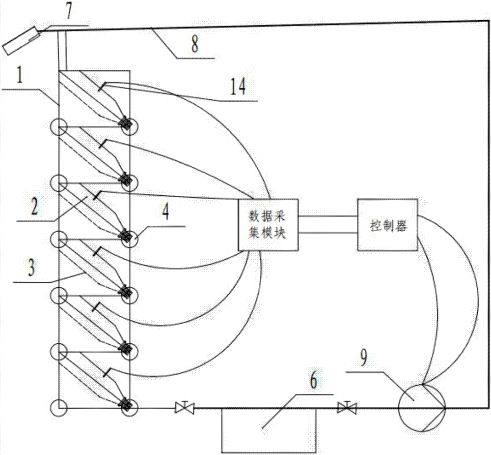
[0019] Embodiment 1: as Figure 1-Figure 4 As shown, a water recovery device for a plant wall, which includes a return water branch pipe 4 and a return water main pipe 5, the return water branch pipe 4 is fixedly connected to the rear side of the plastic-steel exterior wall 1, and the return water branch pipe 4 is respectively connected to each row The bottle mouth of each mineral water bottle 2 lower ends, one end of the backwater branch pipe 4 is sealed, and the other end is connected on the backwater main pipeline 5, and the backwater main pipeline 5 is connected to the sump 6.

[0020] Preferably, a grate 19 is provided at the water inlet and outlet of the above-mentioned sump 6 .

[0021] Preferably, the water collecting tank 6 is provided with a drain pipe 20 near the top side wall.

[0022] Preferably, the above-mentioned sump 6 is provided with a liquid level sensor 22 .

[0023] Preferably, the above-mentioned return water branch pipe 4 is connected to the return wa...

Embodiment 2

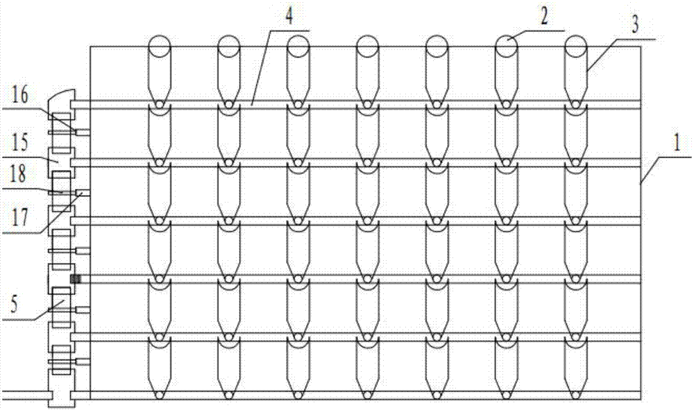
[0026] Embodiment 2: as Figure 1-Figure 4 As shown, the above-mentioned recovery device is used for a plant wall, and the plant wall includes a plastic steel outer wall 1 and a mineral water bottle 2. The plastic steel outer wall 1 is provided with multiple rows of placement grooves 3 inclined downward from the outside to the inside, and each row of each place A mineral water bottle 2 is placed obliquely in the groove 3. The mouth of the mineral water bottle 2 faces inwardly and downwardly, and its upper end opening faces outwardly upwardly. The inside of the bottle is used for planting plants. Placed in the tank, it is convenient to load, unload and replace plastic bottles. Mineral water bottles are recycled and used, and the production cost is greatly reduced. Simple, easy to disassemble and operate.

[0027] Preferably, a shower head 7 is arranged on the outer side of the plastic-steel exterior wall 1. The shower head 7 is mechanically rotating. The shower head 7 is conne...


PUM


Abstract

The invention discloses a water recovery device for a plant wall. The water recovery device comprises water return branch pipes and a main water return pipeline, the water return branch pipes are fixedly connected to the rear side of a plastic-steel external wall and connected with openings in lower ends of water bottles respectively, and one end of each water return branch is sealed while the other end of each water return branch is connected to the main water return pipeline which is connected to a water collection tank. By communication of the bottom ends of the water bottles with the water collection tank through the main water return pipeline and the water return branch pipes, residual water recycling can be realized so as to reduce waste of water resources, rainwater can be recycled in rainy days so as to increase applications of the main water return pipeline and the water return branch pipes, and operation safety of an operator can be guaranteed owing to ground dryness. Further, the water recovery device for the plant wall has advantages of simple structure, low cost and convenience in mounting, demounting and maintenance.

Description

technical field [0001] The invention belongs to the technical field of gardening equipment, and in particular relates to a water recovery device for a plant wall. Background technique [0002] The new environmentally friendly plant wall is suitable for outdoor greening decoration, low light intensity, poor ventilation and other narrow spaces, such as narrow corridors and other places, but the existing plant wall will drip all over the ground after being sprinkled, resulting in waste of water resources. Wet and slippery ground can easily lead to safety accidents. Contents of the invention [0003] The technical problem to be solved by the present invention is: to provide a water recovery device for plant walls, realize the recycling of water resources, reduce the waste of water resources, and keep the ground dry, providing operator safety, so as to solve the above-mentioned prior art problems in . [0004] The technical solution adopted by the present invention is: a wate...

Claims


Application Information

Patent Timeline
IPC IPC(8): A01G27/00
CPCA01G27/00A01G27/003A01G27/008
Inventor 张春旺李绍泉
Owner GUIZHOU UNIV
Why Eureka
Try Eureka