Side-flanging die structure

A technology of side flanging and mold mechanism, which is applied in the field of stamping molds for auto parts, can solve problems such as increased procedures, complex mold structure, and complicated process methods, and achieve the effects of increasing work efficiency and simplifying the stamping process

Inactive Publication Date: 2017-08-29
CHERY AUTOMOBILE CO LTD
View PDF6 Cites 2 Cited by
  • Summary
  • Abstract
  • Description
  • Claims
  • Application Information

AI Technical Summary

Problems solved by technology

In the prior art, the traditional process of flanging from the outside is usually used. The mold structure of this traditional process is complicated, and it usually conflicts with other process contents during the processing. If it is necessary to adjust the part and increase the mold fit, it is often Need to increase the process
The rapid development of the automobile industry is closely related to cost reduction. From the perspective of stamping technology, the traditional process method is more complicated, and the mold structure is complex, the cost is high, and the processing efficiency is low.

Method used


Image

  • Side-flanging die structure
  • Side-flanging die structure
  • Side-flanging die structure

Examples


Embodiment Construction

[0010] combined with Figure 1~4 The present invention is further described:

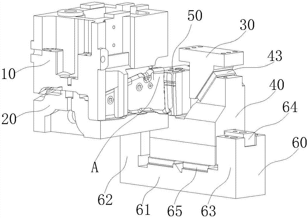
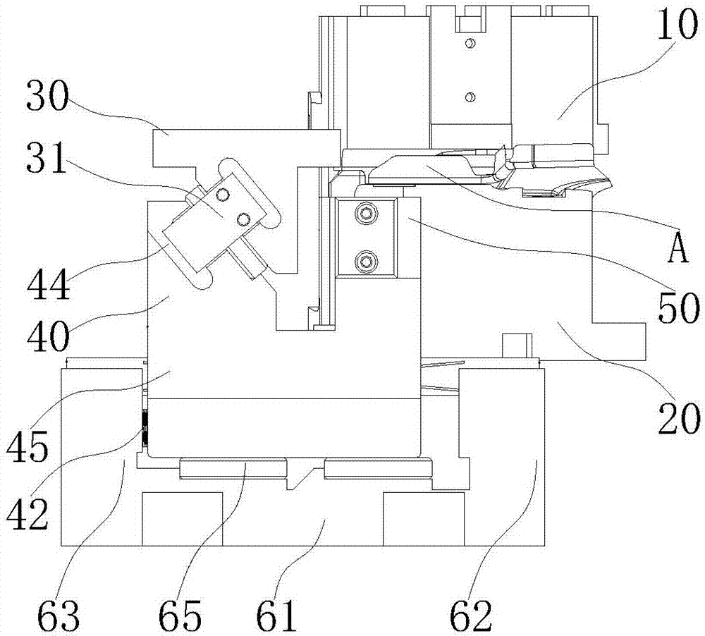
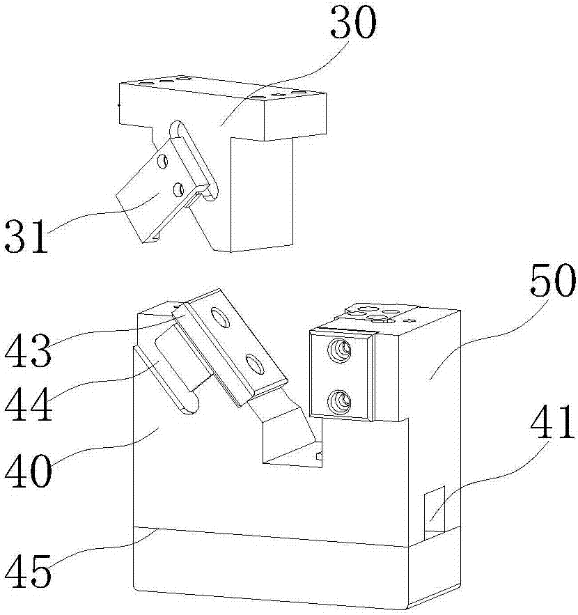
[0011] A side flanging mold mechanism, the pressing core 10 and the fixed lower mold 20 are molded together to shape the workpiece A and maintain a clamping state, and the area to be flanged of the workpiece A protrudes to the pressing core 10 and the fixed lower mold 20. Outside the forming area of ​​the fixed lower mold 20, the drive block 30 is matched with the sliding wedge 40 and arranged opposite to the area to be flanged of the workpiece A. The sliding wedge 40 is connected to the flanging tool 50, and the area to be flanged and The boundary line between the forming surfaces of the workpiece A is located on one side of the flanging tool 50 close to the fixed lower mold 20 and is always on the traveling route of this side, and the pressing driving block 30 collides with the sliding wedge 40 to cause relative slippage and produce The beveling force pushes the sliding wedge 40 to move in a hori...


PUM


Abstract

The invention discloses a side-flanging die mechanism. A material pressing core and a fixed lower die are compounded to form a product and keep a clamping state. A to-be-flanged area of the product protrudes to the exterior of a forming area of the material pressing core and the fixed lower die. A driving block and a sliding slanting wedge are matched correspondingly and arranged relative to the to-be-flanged area of the product. The sliding slanting wedge is connected with a flanging cutter. The junction line between the to-be-flanged area and the forming surface of the product is located on the side face, close to the fixed lower die, of the flanging cutter and is always on an advancing route of the side face. The driving block is pressed down to abut against the sliding slanting wedge to make relative slipping, and produced slanting cutting force pushes the sliding slanting wedge to move in the horizontal direction far from the fixed lower die. The sliding slanting wedge drives the flanging cutter to complete the side flanging action of the to-be-flanged area. The sliding slanting wedge drives the flanging cutter to move in the horizontal direction far from the fixed lower die, namely, the to-be-flanged area is subjected to horizontal side flanging from inside to outside, the stamping process is simplified, and working efficiency is improved.

Description

technical field [0001] The invention belongs to the field of stamping dies for auto parts, in particular to a side flanging die mechanism. Background technique [0002] Automobile panel flanging refers to a stamping process that turns the edge of the hole and the outer edge of the part into a vertical wall under the action of the mold. In the prior art, the traditional process of flanging from the outside is usually used. The mold structure of this traditional process is complicated, and it usually conflicts with other process contents during the processing. If it is necessary to adjust the part and increase the mold fit, it is often Need to increase the process. The rapid development of the automobile industry is closely related to cost reduction. From the perspective of stamping technology, the traditional process method is more complicated, and the mold structure is complex, the cost is high, and the processing efficiency is low. Contents of the invention [0003] The...

Claims


Application Information

Patent Timeline
Patent Type & Authority Applications(China)
IPC IPC(8): B21D37/12B21D19/08
CPCB21D37/12B21D19/08
Inventor 韦佳李旭李伟
Owner CHERY AUTOMOBILE CO LTD
Why Eureka
Try Eureka