Crowned tooth universal drive shaft

A universal transmission and drum-shaped tooth technology, which is applied in the field of transmission shafts, can solve problems such as poor sealing effect, unreliable lubrication, and complex structure, and achieve the effect of eliminating gaps, preventing lubricating oil leakage, and good sealing effect

Active Publication Date: 2017-08-29
LOUDI JIAHUA MACHINERY
View PDF7 Cites 2 Cited by
  • Summary
  • Abstract
  • Description
  • Claims
  • Application Information

AI Technical Summary

Problems solved by technology

At present, no matter the equipment imported from abroad (such as Germany or Japan) or the domestic self-produced device, there are problems of poor sealing and oil leakage at the connection of the drive shaft, which seriously affects production and equipment life. The transmission shaft used on the production line adopts a self-storage grease lubrication device. Although this lubrication device has a simple structure and relatively low manufacturing cost, the lubrication is not reliable; while the transmission shaft on the hot-rolled plate production line adopts an external forced oil supply lubrication device , although this kind of device has reliable lubrication and good lubrication effect, but due to the complex structure and high cost of the oil supply device, and the seal is easily damaged, the transmission shaft has serious oil leakage and the sealing effect is extremely poor, which has a great impact on production.
Although many solutions have been proposed by those skilled in the art, so far there is no relevant report about completely solving the long-term reliable sealing of the transmission shaft and the problem of no oil leakage

Method used


Image

  • Crowned tooth universal drive shaft
  • Crowned tooth universal drive shaft
  • Crowned tooth universal drive shaft

Examples


Embodiment Construction

[0022] The specific implementation manners of the present invention will be further described in detail below in conjunction with the accompanying drawings.

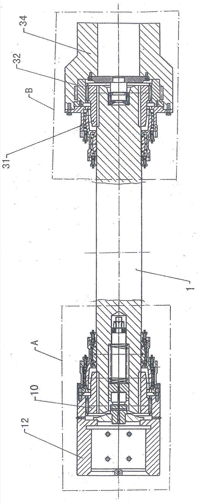
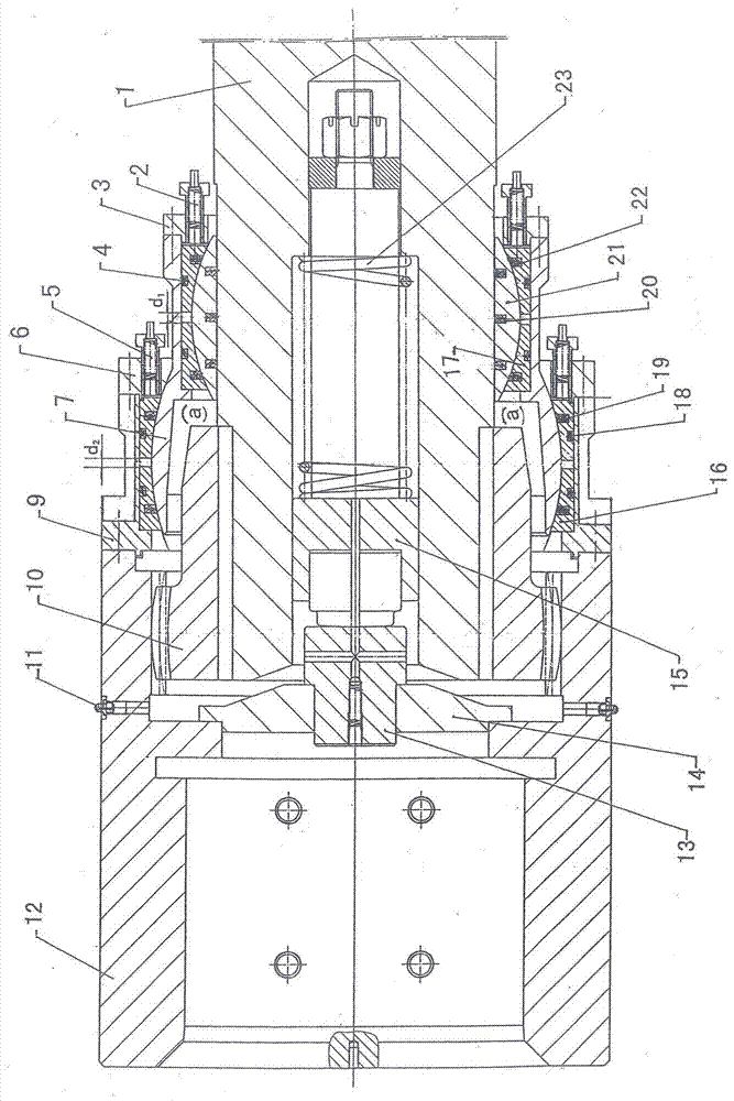
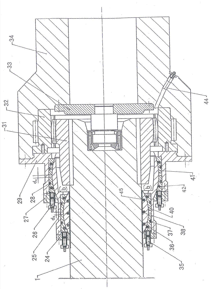
[0023] (As shown in the accompanying drawings) The drum-shaped gear universal transmission shaft of the present invention is mainly designed for the transmission shaft connected with the power part and the roll part of the hot-rolled plate production line or cold-rolled plate production line. It includes shaft body 1, Left first elastic compensator 2, left second elastic compensator 5, right second elastic compensator 35, right second elastic compensator 26, left first pressure ring 3, left second pressure ring 6, left third pressure ring Ring 9, right first pressure ring 24, right second pressure ring 27, right third pressure ring 29, left first sealing ring 4, left second sealing ring 22, left third sealing ring 20, left fourth sealing ring 19. Left fifth sealing ring 18, right first sealing ring 37, right second seali...


PUM


Abstract

The invention discloses a crowned tooth universal drive shaft. Left / right crowned tooth external toothed sleeves and left / right crowned tooth internal toothed rings matched with the left-right crowned tooth external toothed sleeves are installed on the peripheries of the two ends of a shaft body in a key-groove mode, and internal / external crowned teeth machined on the external toothed sleeves and the internal toothed rings are mutually engaged. Left / right internal convex spherical sleeves, external concave spherical sleeves and external convex spherical sleeves are symmetrically installed on the positions, close to the external toothed sleeves, on the periphery of the shaft body, and a plurality of layers of sealing rings are arranged among the left / right internal convex spherical sleeves, the left / right external concave spherical sleeves and the left / right external convex spherical sleeves. Left / right internal concave spherical sleeves and pressing rings are further installed on the spherical surfaces of the left / right external convex spherical sleeves, a plurality of elastic compensators are assembled on the pressing rings connected with the external convex spherical sleeves and the middle pressing rings so that appropriate intervals can be reserved between concave spherical movable sleeves and concave spherical fixed sleeves on the left / right concave spherical sleeves, and lubricating oil cavities are formed between the left / right external toothed sleeves and the external convex spherical sleeves. The drive shaft is driven by the crowned teeth so that universal drive can be achieved, the stress end and the force transmitting end of the drive shaft are sealed by double spherical surfaces, the sealing effect is good, oil leakage does not occur, running is stable, and the crowned tooth universal drive shaft has popularization value.

Description

technical field [0001] The invention relates to a transmission shaft, in particular to a drum-shaped gear universal transmission shaft used in a hot-rolled plate production line or a cold-rolled plate production line and matched between a roll and a motor. Background technique [0002] The high-speed transmission shaft is the transmission mechanism installed between the output end of the motor gearbox and the roll in the hot-rolled / cold-rolled plate production line. Its safe operation and sealing performance play a key role in stabilizing hot-rolled or cold-rolled production and quality assurance. At present, no matter the equipment imported from abroad (such as Germany or Japan) or the domestic self-produced device, there are problems of poor sealing and oil leakage at the connection of the drive shaft, which seriously affects production and equipment life. The transmission shaft used in the production line adopts a self-storage grease lubrication device. Although this type...

Claims


Application Information

Patent Timeline
Patent Type & Authority Applications(China)
IPC IPC(8): F16D3/18B21B35/14
CPCF16D3/18B21B35/142
Inventor 戴光荣
Owner LOUDI JIAHUA MACHINERY
Why Eureka
Try Eureka