Sensor assembly and method for manufacturing sensor assembly

A technology of sensor components and manufacturing methods, applied in the direction of instruments, power metering, measuring devices, etc., capable of solving problems such as reduced reliability of magnetic sensor circuits

Active Publication Date: 2017-08-29
JTEKT CORP
View PDF13 Cites 4 Cited by
  • Summary
  • Abstract
  • Description
  • Claims
  • Application Information

AI Technical Summary

Problems solved by technology

Furthermore, when high-temperature and high-pressure resin comes into contact with the magnetic sensor circuit during insert molding, there is a possibility that the reliability of the magnetic sensor circuit will be reduced.

Method used


Image

  • Sensor assembly and method for manufacturing sensor assembly
  • Sensor assembly and method for manufacturing sensor assembly
  • Sensor assembly and method for manufacturing sensor assembly

Examples


no. 3 approach

[0094] Hereinafter, the third embodiment will be described focusing on points different from the first embodiment with reference to the drawings.

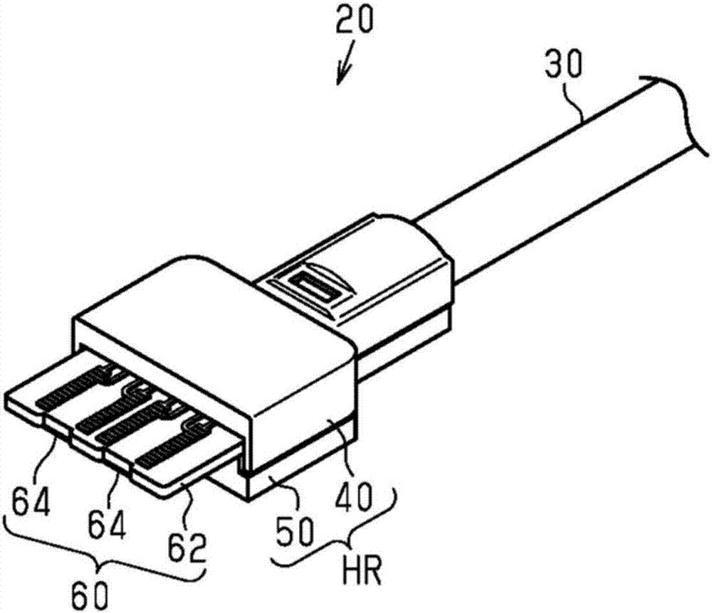
[0095] Figure 9 A cross-sectional structure of the holder HR according to this embodiment is shown in . In addition, in Figure 9 in, for image 3 Components corresponding to those shown in FIG. 2 and 4 are denoted by the same reference numerals for convenience. Such as Figure 9 As shown, in the present embodiment, the holder HR is integrally formed of the sensor housing part SH in which a part of the magnetic sensor circuit 60 is housed, and the harness housing part HH in which a part of the wire harness 30 is housed. Specifically, the sensor housing part SH and the harness housing part HH are configured by the first holder part 40 and the second holder part 50 . Here, the first holder portion 40 of the harness housing portion HH extends in a direction opposite to the direction in which the substrate 62 protrudes from the h...


PUM


Abstract

The invention relates to a sensor assembly that can prevent the reliability of a magnetic sensor circuit from being lowered, and a method for manufacturing the sensor assembly. A first holder part (40) has a first holder side wall (44) protruded from a first holder base part (42). The first holder side wall (44) is a thin plate member protruding to a second holder part (50) side, from a first holder main surface (42a) of the first holder base part (42) that faces a base plate (62). The first holder side wall (44) is provided to each side of the first holder base part (42) in the width direction W of the base plate (62). The first holder side wall (44) is inclined to the inner side of the base plate (62) in the width direction W until it becomes in contact with an end surface (54b) of a small base part (54) of a second holder part (50). A first holder side wall outer surface (44a), which is the outer surface of the first holder side wall (44) in the width direction W, is in contact with a case (20).

Description

[0001] This application claims the priority of Japanese Patent Application No. 2015-236656 filed on December 3, 2015, and Japanese Patent Application No. 2016-005565 filed on January 14, 2016, and cites the specification, attached Figures and the entire contents of the abstract of the instruction manual. technical field [0002] The present invention relates to a sensor unit constituting a torque sensor and a method of manufacturing the sensor unit. Background technique [0003] Conventionally, for example, Japanese Patent Application Laid-Open No. 2015-31600 describes a technique in which a magnetic sensor circuit including a magnetic induction element constituting a torque sensor is surrounded by resin by insert molding. [0004] However, when insert molding a resin, the temperature of the resin is increased to impart fluidity, and the resin is increased to a high pressure in order to pour the resin into the mold. Furthermore, when high-temperature and high-pressure resin...

Claims


Application Information

Patent Timeline
IPC IPC(8): G01L3/10
CPCG01L3/104
Inventor 外山祐一
Owner JTEKT CORP
Why Eureka
Try Eureka