Glass laminate, method for producing electronic device, method for producing glass laminate, and glass plate package
A technology of electronic devices and laminates, which is applied in the direction of electronic equipment, chemical instruments and methods, glass/slag layered products, etc., and can solve the problems of reduced handling of glass substrates
- Summary
- Abstract
- Description
- Claims
- Application Information
AI Technical Summary
Problems solved by technology
Method used
Image
Examples
no. 1 Embodiment approach
[0040] Hereinafter, first, one embodiment (first embodiment) of the glass laminate of the present invention will be described in detail.
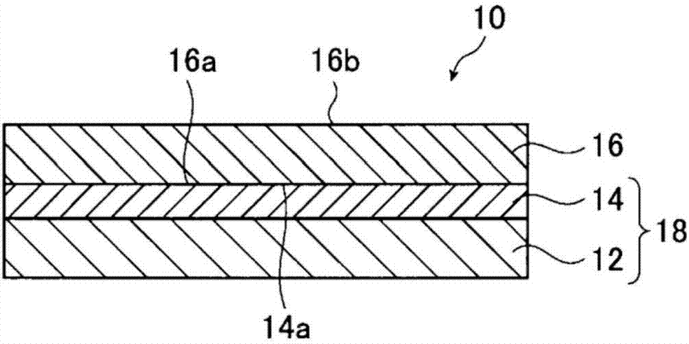
[0041] figure 1 It is a cross-sectional schematic diagram of an example of the glass laminated body of this invention.
[0042] like figure 1 As shown, the glass laminated body 10 is a laminated body which has the layer of the support base material 12, the layer of the glass substrate 16, and the adhesive layer 14 which exists between these layers. One surface of the adhesive layer 14 is in contact with the layer of the support base 12 , and the other surface is in contact with the first main surface 16 a of the glass substrate 16 . The two-layer portion formed by the layer of the support base material 12 and the adhesive layer 14 is used to reinforce the glass substrate 16 in a member forming process for manufacturing members for electronic devices such as liquid crystal panels.
[0043]This glass laminated body 10 is used until the m...
no. 2 Embodiment approach
[0177] Hereinafter, another embodiment (second embodiment) of the glass laminate of the present invention will be described in detail.
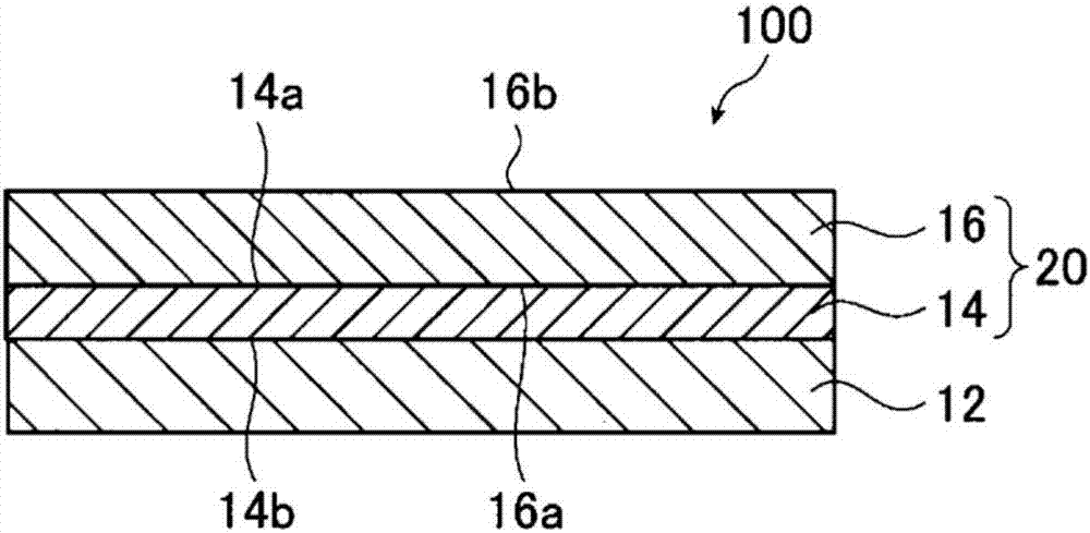
[0178] image 3 It is a cross-sectional schematic diagram of an example of the glass laminated body of this invention.
[0179] like image 3 As shown, the glass laminated body 100 is a laminated body which has the layer of the support base material 12, the layer of the glass substrate 16, and the adhesive layer 14 which exists between them. One surface of the adhesive layer 14 is in contact with the layer of the support base 12 , and the other surface is in contact with the first main surface 16 a of the glass substrate 16 .
[0180] constitute image 3 Each layer of the glass laminated body 100 (support base material 12, glass substrate 16, adhesive layer 14) has the same meaning as each layer constituting the above-mentioned glass laminated body 10, and description thereof is omitted here.
[0181] image 3 The glass laminate 100 with...
Embodiment 1
[0233] First, each end face of the support base was chamfered using a #500 diamond wheel manufactured by KURE GRINDING WHEELL CO., LTD. Next, after cleaning the surface of the support substrate with pure water with a brush, in a clean room (cleanliness: Class 1000), silicone for solvent-free addition reaction release paper (Shin-Etsu Silicone Co., Ltd. A mixture of 100 parts by mass of KNS-320A) and 2 parts by mass of a platinum-based catalyst (CAT-PL-56, manufactured by Shin-Etsu Silicone Co., Ltd.) was coated on the surface of the cleaned support substrate by screen printing (coating amount 15g / m 2 ), heated and cured at 100° C. for 3 minutes to form a silicone resin layer with a film thickness of 15 μm.
[0234] Next, after cleaning the surface of the glass substrate on the side in contact with the silicone resin layer by washing with pure water with a brush, the silicone resin layer on the supporting substrate and the glass substrate were bonded together by vacuum pressin...
PUM
| Property | Measurement | Unit |
|---|---|---|
| thickness | aaaaa | aaaaa |
| diameter | aaaaa | aaaaa |
| diameter | aaaaa | aaaaa |
Abstract
Description
Claims
Application Information
 - R&D
- Intellectual Property
- Life Sciences
- Materials
- Tech Scout
- Unparalleled Data Quality
- Higher Quality Content
- 60% Fewer Hallucinations
Browse by: Latest US Patents, China's latest patents, Technical Efficacy Thesaurus, Application Domain, Technology Topic, Popular Technical Reports.
© 2025 PatSnap. All rights reserved.Legal|Privacy policy|Modern Slavery Act Transparency Statement|Sitemap|About US| Contact US: help@patsnap.com


