Method for carrying out work on a rotor and associated foil

A rotor and lining technology, applied in the field of implementation operations, can solve the problems of time-consuming replacement and inability to repair, etc., and achieve the effect of improving service life and improving contact conditions

Active Publication Date: 2017-08-29
SAFRAN AIRCRAFT ENGINES SAS
View PDF5 Cites 7 Cited by
  • Summary
  • Abstract
  • Description
  • Claims
  • Application Information

AI Technical Summary

Problems solved by technology

This phenomenon is particularly annoying because the rotor (including the drum) is a relatively expensive component, and these components ar...

Method used


Image

  • Method for carrying out work on a rotor and associated foil
  • Method for carrying out work on a rotor and associated foil
  • Method for carrying out work on a rotor and associated foil

Examples


Embodiment Construction

[0047] Before specifically presenting the invention, therefore, according to the known state of the art of document EP2762681, when the rotor damaged and thus required to be ground is a low-pressure compressor drum, figure 1 and figure 2 The operating environment of the present invention is shown.

[0048] In fact, the invention is applicable, within the limits specified, to another type of rotor fitted with low-pressure compressor drum blades; however, because of its position, mass, volume, and constraints involved in the It's all specific.

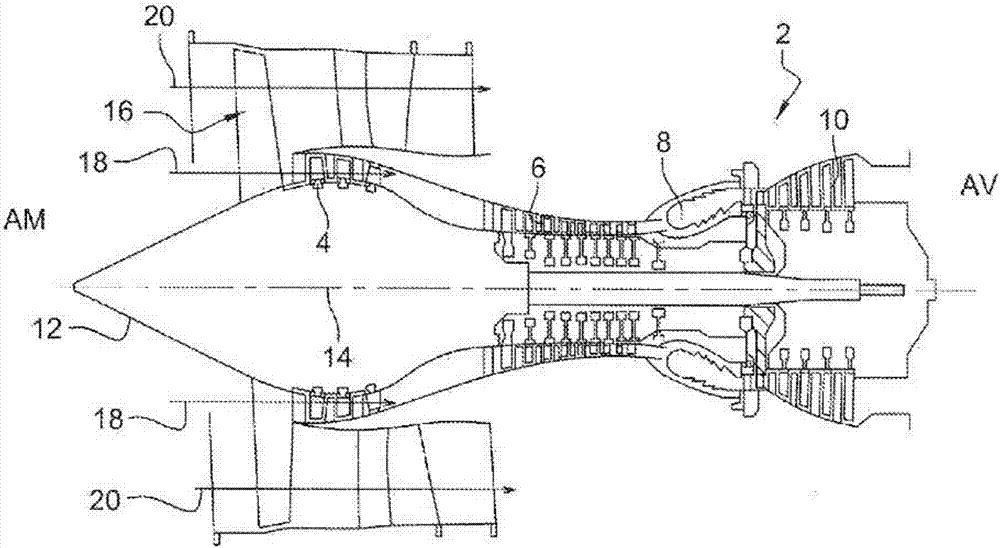
[0049] figure 1 A two-way turbine 2 is shown. Such a turbomachine 2 comprises, axially from upstream (AM) to downstream (AV), a low-pressure compressor 4 , a high-pressure compressor 6 , a combustion chamber 8 and one or more turbine stages 10 . In operation, the mechanical power of the turbine 10 , transmitted via the central shaft to the rotor 12 , drives the two compressors 4 and 6 . Rotation of the rotor 12 about its axis of rota...


PUM


Abstract

The invention relates to a method for carrying out work on a metal turbine engine rotor, such as a drum, in order to maintain the rotor operational, consisting in: grinding an upstream and/or downstream face (343) of a circumferential groove (34) of the rotor, said face having recessed marks that the grinding is intended to remove or at least blur; and placing foils (43) in the groove between the blades of the rotor (24) and the rotor, at least in the area where the face has been ground.

Description

technical field [0001] The present invention relates to a method of performing work to keep an existing aircraft turbine rotor, such as a low pressure compressor rotor drum, in operation. [0002] The invention also relates to foils used on such rotor blades, and assemblies consisting of the blade and the foils below the blade and around the root of the blade. Background technique [0003] Preferably the turbine is an aircraft turbine engine. In addition, in this application, the axial direction is defined as a direction parallel to the rotation axis of the fan. Furthermore, upstream and downstream of a component are defined relative to the normal direction of airflow within the turbine engine. The radial direction is a direction perpendicular to the aforementioned axial direction, and the terms "inner" and "outer" refer to being relatively closer and farther away from the axis of rotation in the radial direction, respectively. [0004] Also, the rotors described here: ...

Claims


Application Information

Patent Timeline
IPC IPC(8): F01D5/00F01D5/30
CPCF01D5/005F01D5/3038F05D2230/80Y02T50/60
Inventor 安东尼·帕特里斯·玛丽·戴斯雷麦克思帕特里克·让-路易斯·雷赫兹
Owner SAFRAN AIRCRAFT ENGINES SAS
Why Eureka
Try Eureka