Method for performing work on a rotor and related linings

A rotor and lining technology, applied in the field of operation, can solve the problems of inability to repair and time-consuming replacement, and achieve the effect of improving service life and improving contact conditions.

Active Publication Date: 2019-08-13
SAFRAN AIRCRAFT ENGINES SAS
View PDF5 Cites 0 Cited by
  • Summary
  • Abstract
  • Description
  • Claims
  • Application Information

AI Technical Summary

Problems solved by technology

This phenomenon is particularly annoying because the rotor (including the drum) is a relatively expensive component, and these components are time-consuming to replace
[0008] In fact, especially on drums, such substandard parts found during repairs are scrapped as they are beyond repair

Method used


Image

  • Method for performing work on a rotor and related linings
  • Method for performing work on a rotor and related linings
  • Method for performing work on a rotor and related linings

Examples


Embodiment Construction

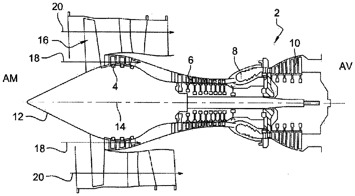
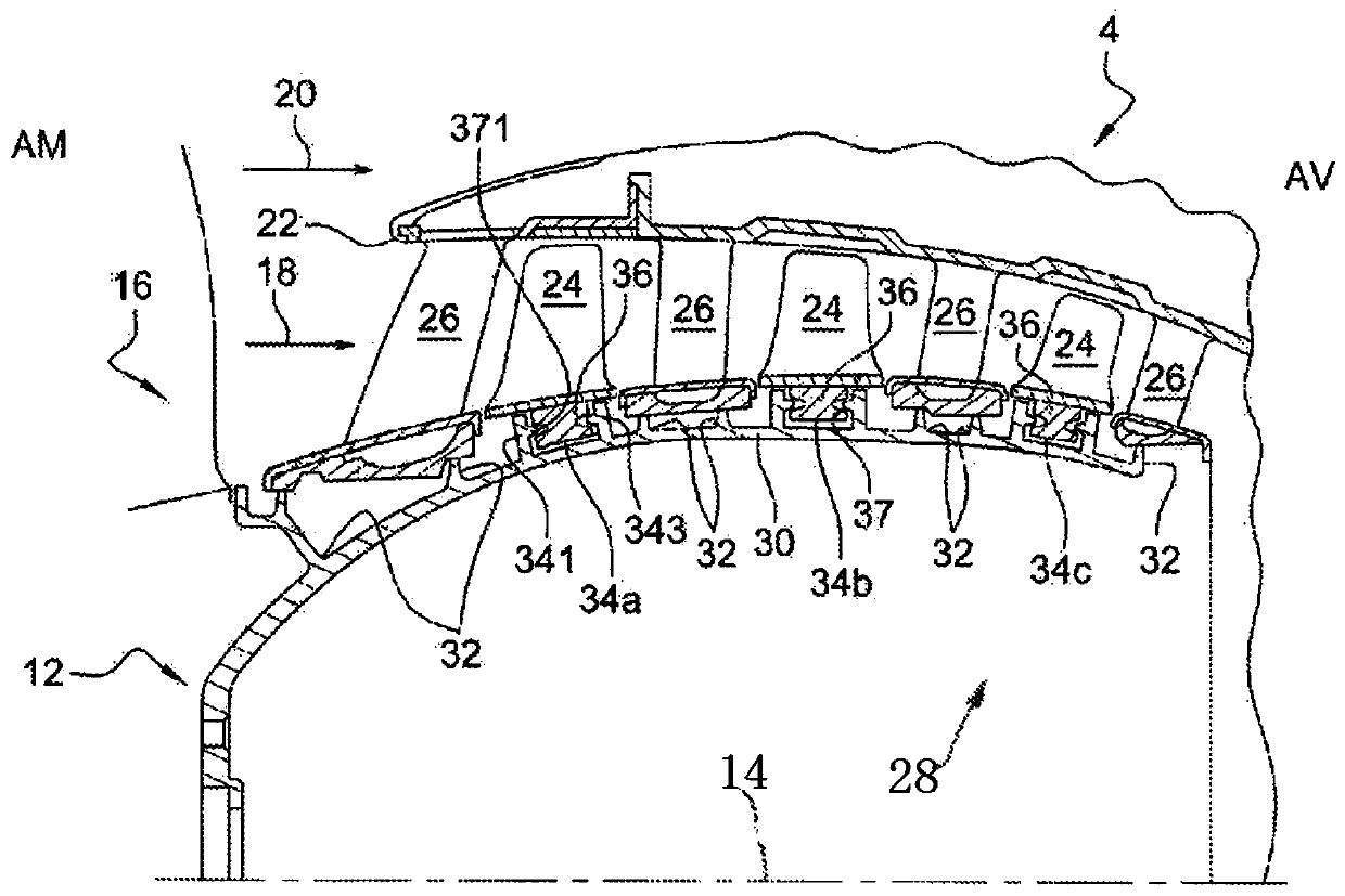
[0047] Before specifically introducing the present invention, therefore, according to the known state of the art in document EP2762681, when the rotor that is damaged and needs to be ground is a low-pressure compressor drum, figure 1 with figure 2 The operating environment of the present invention is shown.

[0048] In fact, the present invention is applicable to another rotor equipped with low-pressure compressor drum blades within the specified scope; however, because of its position, mass, volume, and constraints in the engine, this component They are all specific.

[0049] figure 1 A two-way turbine 2 is shown. Such a turbine 2 includes a low-pressure compressor 4, a high-pressure compressor 6, a combustion chamber 8 and one or more turbine stages 10 in order from upstream (AM) to downstream (AV) in the axial direction. In operation, the mechanical power of the turbine 10 transmitted to the rotor 12 via the central shaft drives the two compressors 4 and 6. Rotation of the ro...


PUM


Abstract

The present invention provides a method of performing work on a metal turbine engine rotor, such as a drum, for maintaining the rotor in an operable condition, comprising: Grinding, with concave marks on said face, said grinding is intended to remove said marks or at least to obscure them, and a lining (43) is placed in the groove between the rotor blades (24) and the rotor, at least In areas where the face has been ground.

Description

Technical field [0001] The present invention relates to a method of performing operations to keep existing aircraft turbine rotors (such as low-pressure compressor rotor drums) in operation. [0002] The present invention also relates to the linings (foils) used on the rotor blades of this kind, and the components composed of the blades and the linings on and around the blade root. Background technique [0003] Preferably the turbine is an aircraft turbine engine. In addition, in this application, the axial direction is defined as a direction parallel to the rotation axis of the fan. In addition, the upstream and downstream of the component are defined as the normal direction of airflow in the turbine engine. The radial direction is the direction upright to the above-mentioned axial direction, and the terms "inner" and "outer" respectively refer to being relatively closer to and farther from the axis of rotation in the radial direction. [0004] In addition, the rotor described he...

Claims


Application Information

Patent Timeline
Patent Type & Authority Patents(China)
IPC IPC(8): F01D5/00F01D5/30
CPCF01D5/005F01D5/3038F05D2230/80Y02T50/60
Inventor 安东尼·帕特里斯·玛丽·戴斯雷麦克思帕特里克·让-路易斯·雷赫兹
Owner SAFRAN AIRCRAFT ENGINES SAS
Why Eureka
Try Eureka