Transmission and method for adjusting the circumferential backlash of the transmission

A technology of transmission mechanism and adjustment components, which is applied in the direction of anti-centrifugal rotating parts, transmission devices, gear transmission devices, etc., and can solve the problems of maintaining theoretical presets, sinking, and no longer maintaining

Active Publication Date: 2017-08-29
LENZE DRIVES
View PDF7 Cites 8 Cited by
  • Summary
  • Abstract
  • Description
  • Claims
  • Application Information

AI Technical Summary

Problems solved by technology

[0007] In addition to the selective and costly mounting of the spacer, which can sometimes only be achieved unsatisfactorily, it has also been found to be disadvantageous that the spacer sinks during operation. And the position of the outer ring of the corresponding bearing, which is adjusted by the spacer, is no longer maintained, thus (dadurch) no longer maintains its theoretical presupposition (Soll-Vorgabe)

Method used


Image

  • Transmission and method for adjusting the circumferential backlash of the transmission
  • Transmission and method for adjusting the circumferential backlash of the transmission
  • Transmission and method for adjusting the circumferential backlash of the transmission

Examples


Embodiment Construction

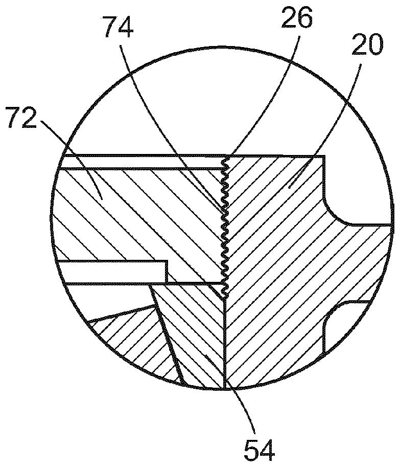
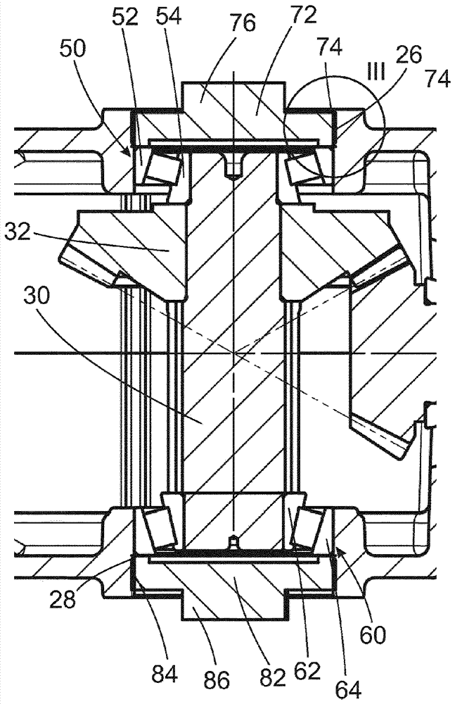
[0032] figure 1 The transmission 10 according to the invention is shown, which is distinguished by two bevel gears 32 , 42 meshing with each other. figure 2 and 3 Details of the transmission are shown in an enlarged view.

[0033] The transmission 10 has a housing 20 , wherein the housing is considered to be all sections of the transmission 10 that are stationary relative to one another after assembly. The housing 20 delimits a housing interior in which two mutually non-parallel shafts 30 , 40 are mounted. Two bevel gears 32 , 42 meshing with each other are fixed on said shaft 30 , 40 .

[0034] In order to be able to adjust the rotational play of the bevel gears 32 , 42 according to the field of application, the first shaft 30 is axially displaceable by means of an adjusting device 70 , 80 . The mode of operation of the adjusting device 70 , 80 is explained below.

[0035] The first shaft 30 is supported by means of two rolling bearings 50 , 60 which are each designed a...


PUM


Abstract

The invention relates to a transmission (10) that has a housing (20) and a first and a second shaft (30, 40), each of which has a bevel gear wheel (32, 42), said bevel gear wheels (32, 42) being in meshing engagement with each other. The first shaft (30) with a first bevel gear wheel (32) is designed as an axially adjustable shaft and is supported by two rolling bearings (50, 60) on both sides of the bevel gear wheel (32) for this purpose, and each of the rolling bearings (50, 60) has a shaft-side inner ring (52, 62) and a housing-side outer ring (54, 64). The shaft-side inner rings (52, 62) are provided on the first shaft (30) in a defined axial position, whereas the housing-side outer rings (54, 64) of the rolling bearings (50, 60) are guided on respective housing-side support surfaces (22, 24) and are restricted from moving towards each other solely by the inner rings and the shaft. The axial position of the housing-side outer rings (54, 64) of the rolling bearings (50, 60) can be adjusted on the side facing away from the bevel gear wheel (32) by a respective adjusting device (70, 80). Each of the adjusting devices (70, 80) has an adjusting element (72, 82) with an outer thread (74, 84) on the respective outer ring (54, 64) side facing away from the bevel gear wheel (32), said outer thread being inserted into a housing-side inner thread (26, 28). The inner thread (26, 28) and the outer thread (74, 84) are designed as fine threads, preferably with a pitch of maximally 0.75 mm.

Description

technical field [0001] The invention relates to a transmission with two bevel gears meshing with each other. Background technique [0002] Such transmissions are used in a wide variety of fields of mechanical engineering (maschinenbauliche) application. Torque is transmitted from one shaft to a second non-parallel shaft via two bevel gears. [0003] In gears of this type it is often desirable to adjust the rotational play (Verdrehspiel), that is to say the rotatability of one of the shafts without rotation of the second shaft and / or the axial pretension of the shaft or The axial clearance is adjusted according to the specific situation (fallweise). It is necessary here that these parameters can also be adjusted as easily as possible after assembly of the transmission. [0004] Heretofore conventional approaches have provided that one of the shafts is designed to be axially displaceable. This is usually achieved by providing spacers on the outside of the corresponding out...

Claims


Application Information

Patent Timeline
Patent Type & Authority Applications(China)
IPC IPC(8): F16H57/022F16H57/038F16C25/06
CPCF16C25/06F16H57/022F16H57/038F16H2057/0221F16C23/06F16C19/547F16C2226/60F16C2361/61F16C23/08F16H1/14F16H57/12F16H2057/0225
Inventor H.乌伦布罗克M.哈施克
Owner LENZE DRIVES
Why Eureka
Try Eureka