Radiation integrated antenna unit and multi-array antenna

一种集成天线、多阵列的技术,应用在无线通讯领域,能够解决昂贵开发和实施资源等问题

Active Publication Date: 2017-08-29
TONGYU COMM INC
View PDF6 Cites 20 Cited by
  • Summary
  • Abstract
  • Description
  • Claims
  • Application Information

AI Technical Summary

Problems solved by technology

In addition to expensive development and implementation resources, it also leads to factors such as weight, size and integration flexibility, because different hardware must be designed separately before integration

Method used


Image

  • Radiation integrated antenna unit and multi-array antenna
  • Radiation integrated antenna unit and multi-array antenna
  • Radiation integrated antenna unit and multi-array antenna

Examples


Embodiment Construction

[0042] Specific embodiments of the present invention will be further described below in conjunction with the accompanying drawings.

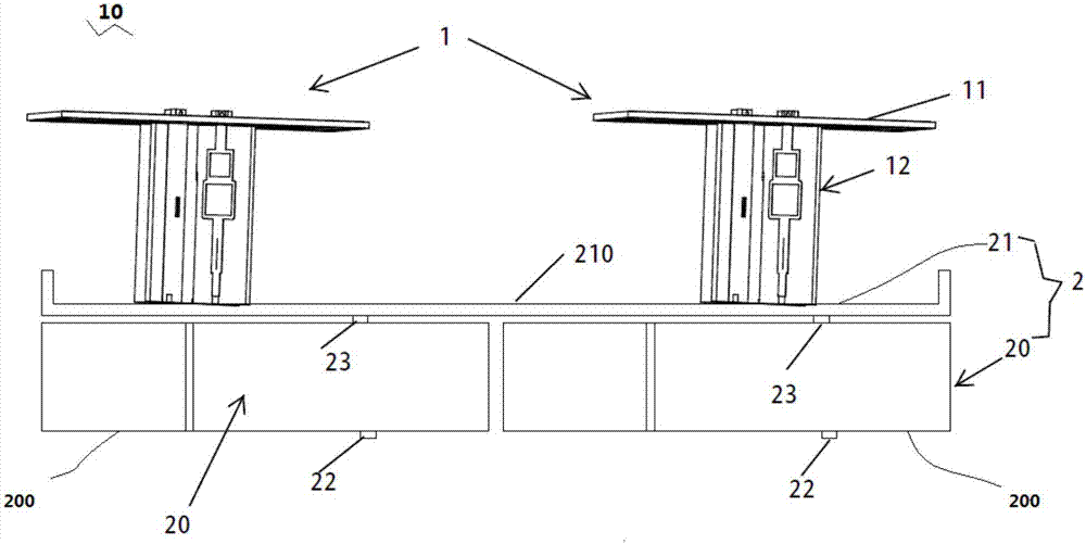
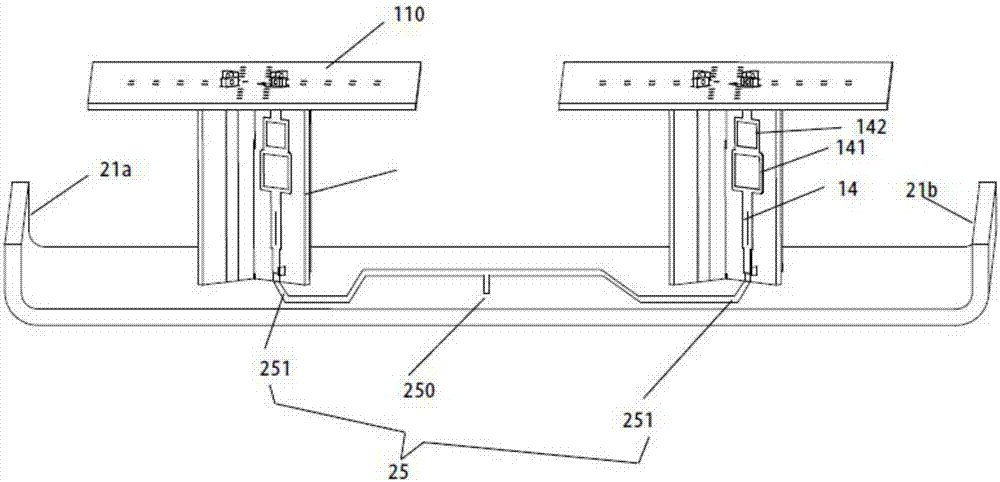
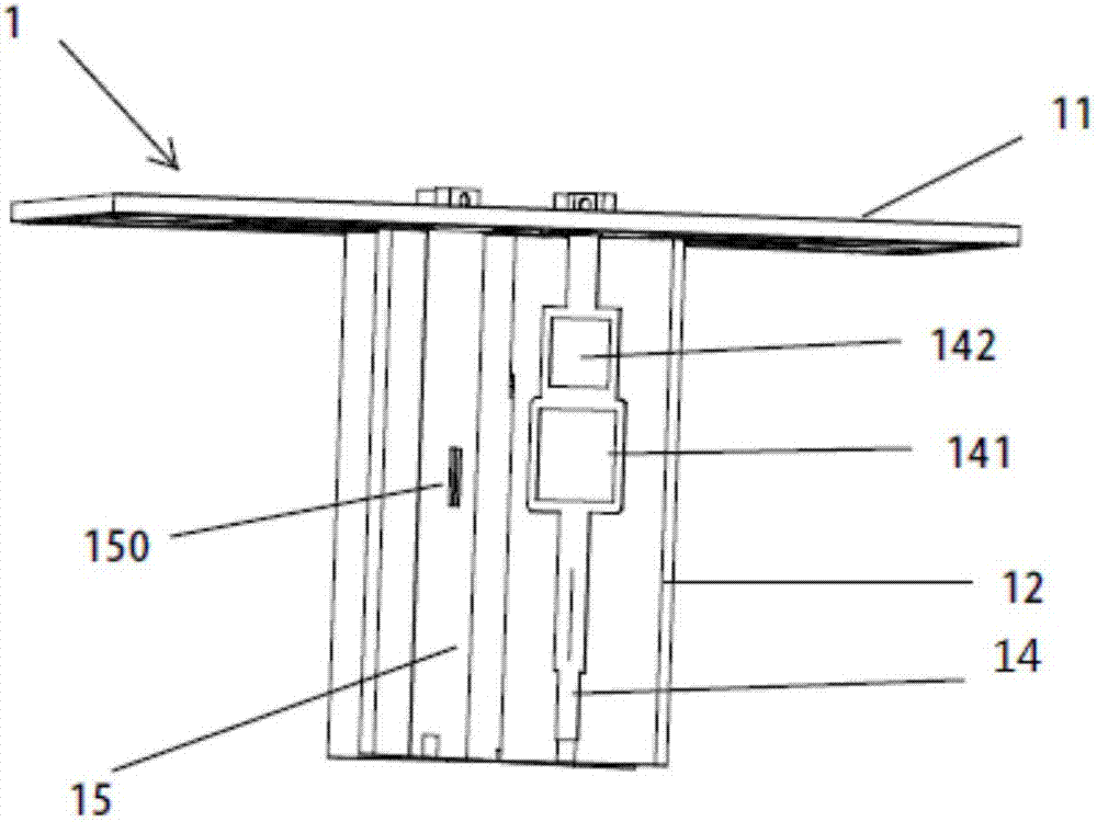
[0043] refer to Figure 1-6 , the radiation integrated antenna unit 10 includes two radiating elements 1 , and two bandpass filters 20 and PCB 21 are integrated into an integrated filtering device 2 supported under the two radiating elements 1 . The integrated filtering means is formed by two bandpass filters 20 and the PCB 21 of said integrated antenna unit 10 . The PCB 21 is used as a filter cover, and the cover is arranged on the tops of the two bandpass filters 20, and simultaneously forms the reflectors of the two radiating elements 1; therefore, the top surface 210 of the PCB 21 is also the reflective surface of the two radiating elements 1 . Two radiating elements 1 extend upward from the top surface 210 of the PCB 21 .

[0044] Correspondingly, in the embodiment of the present invention, the PCB, the filter cover and the reflector are...


PUM


Abstract

The invention provides an integrated antenna unit (10),wherein two polarized radiation components (1) are connected to a PCB (21). The PCB (21) is used as a reflection board and the filter cover for two band-pass filters (20). Each of the band-pass filters is directly connected with a bi-directional power divider (25). The bidirectional power dividers (25) are connected with the polarization of the two radiation components (1). Two parallel walls (21a) (22b) extend towards the edges of the band-pass filters so as to support the cavity of the filter and at the same time to act on the reflection walls. The reflection walls control the radiation components (1) to generate a direction beam 3dB. Further, the multi-array antenna (100) of the invention consists of a plurality of integrated antenna units.

Description

technical field [0001] The invention relates to wireless communication, in particular to a radiation integrated antenna unit and a multi-array antenna. Background technique [0002] Conventional antenna systems suffer from the following challenges: [0003] High-rise building coverage: Limited directional antennas (in the azimuth / elevation plane) lead to limitations in high-order partitioning. [0004] Macro and uplink coverage capability and capacity limitations: For a given allocated time-frequency, inter-cell and intra-cell interference are effectively nulled due to only a small number of existing antennas capable of directing azimuth narrow beams, so the There are still challenges in the reuse process. In addition, with business expansion, it is difficult to obtain new sites with UL:DL=1:3. [0005] In-building high-capacity development: Even the claimed SU-MIMO is underutilized due to the limited size of user equipment. In addition, the cost of the in-building syste...

Claims


Application Information

Patent Timeline
Patent Type & Authority Applications(China)
IPC IPC(8): H01Q1/52H01Q19/17H01Q1/36H01Q1/50H01Q21/00
CPCH01Q1/36H01Q1/50H01Q1/523H01Q19/17H01Q21/0006H01Q1/246H01Q15/14H01Q21/0075H01Q21/26H01Q21/062H01Q21/0062H01Q15/22
Inventor 萨姆布·杜杜吴中林刘木林伊索拉阿里
Owner TONGYU COMM INC
Why Eureka
Try Eureka