
Robot device with clamping function

A robot and functional technology, applied in the direction of manipulators, manufacturing tools, etc., can solve the problems of high risk, low efficiency, high labor intensity, etc., and achieve the effect of strong carrying capacity, wide application range and reliable work

Pending Publication Date: 2017-09-01
SHENYANG INST OF AUTOMATION - CHINESE ACAD OF SCI +1
View PDF6 Cites 3 Cited by
  • Summary
  • Abstract
  • Description
  • Claims
  • Application Information

AI Technical Summary

Problems solved by technology

Manual inspection is inefficient, labor-intensive, and dangerous; helicopter inspection is expensive, and inspection quality is easily affected by climate

Method used


Image

  • Robot device with clamping function
  • Robot device with clamping function
  • Robot device with clamping function

Examples


Embodiment Construction

[0026] The present invention will be described in further detail below in conjunction with the accompanying drawings.

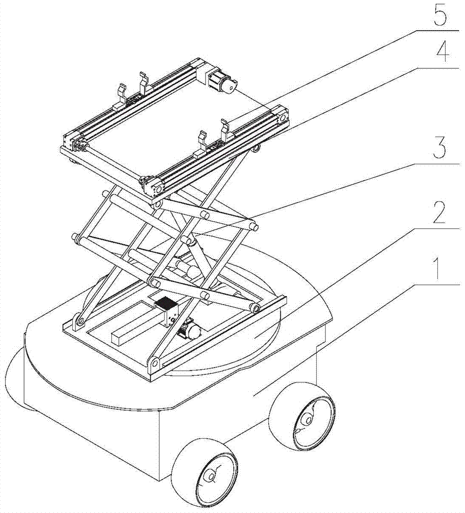
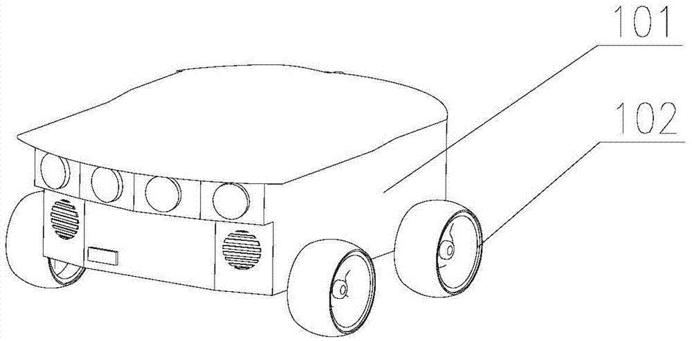
[0027] figure 1 It is a structural schematic diagram of the present invention; as figure 1 As shown, a robot device with a clamping function provided by the present invention includes a mobile vehicle 1, a turntable 2, a lifting platform 3, a connecting platform 4 and a clamping tool 5, wherein the turntable 2 is rotatably installed on the mobile vehicle 1 , the lifting platform 3 is fixedly connected with the turntable 2, the connecting platform 4 is arranged on the top of the lifting platform 3, and the clamping tool 5 is fixedly connected with the connecting platform 4.

[0028] Figure 5 It is a structural schematic diagram of the clamping tool in the present invention; as Figure 5 As shown, the clamping tool 5 includes a clamping motor 501, a first clamping mechanism, a second clamping mechanism and a transmission shaft 505, wherein the first clampin...


PUM


Abstract

The invention relates to a robot device for power transmission and transformation facility detection, in particular to a robot device with a clamping function. The clamping device comprises a moving vehicle, a rotary table, a lifting platform, a connection platform and a clamping tool, wherein the rotary table is rotationally arranged on the moving vehicle, the lifting platform is fixedly connected with the rotary table, the connection platform is arranged on the top of the lifting platform, and the clamping tool is fixedly connected with the connection platform. By combining the moving vehicle and the lifting mechanism, the robot device has the functions of ground walking and operating; by means of the lifting platform, operation tool ascending and descending are achieved, working is reliable, and the bearing capability is high; and the robot device is suitable for robot detection operation under a power transmission and transmission environment, and the application range is wide.

Description

technical field [0001] The invention relates to a detection robot device for power transmission and transformation facilities, in particular to a robot device with a clamping function. Background technique [0002] The transmission line is an extremely important part of the power system. In order to ensure its safe and stable operation, regular inspections are required. At present, the transmission line inspection methods mainly include manual inspection and helicopter inspection. Manual inspections are inefficient, labor-intensive, and dangerous; helicopter inspections are costly and the quality of inspections is easily affected by the climate. Therefore, a robot device for testing power transmission facilities has been developed to replace manual inspections, improve operating efficiency, and reduce labor intensity of workers. Contents of the invention [0003] In view of the above problems, the object of the present invention is to provide a robot device with a clampi...

Claims


Application Information

Patent Timeline
Patent Type & Authority Applications(China)
IPC IPC(8): B25J5/00
CPCB25J5/007
Inventor 李斐明王洪光张景佩刘爱华韩晋东胡明伟桑赵刚孙鹏王瑞珏姜勇
Owner SHENYANG INST OF AUTOMATION - CHINESE ACAD OF SCI
Learn More