Electric feeding machine

A feeder and electric technology, which is applied in the field of feeders for building secondary structural column pouring machines, can solve the problems of complicated transportation procedures, limited use, large volume, etc., and achieves simple transportation procedures, increased stability, and reduced volume. Effect

Pending Publication Date: 2017-09-01
王德宇
View PDF6 Cites 1 Cited by
  • Summary
  • Abstract
  • Description
  • Claims
  • Application Information

AI Technical Summary

Problems solved by technology

But these two methods have obvious limitations when working with carts (including electric carts):
[0003] 1. The transportation process is complicated. First, it is necessary to manually pour the materials in the cart into the receiving hopper, and then start the feeding machine for loading;
[0004] 2. It is inconvenient to move. In order to cooperate with the whole feeding process and save the labor cost of feeding, a cart ramp is generally set up near the hopper. The change of the position of the hopper requires corresponding changes to the cart ramp, which undoubtedly increases The cost of moving the pos

Method used


Image

  • Electric feeding machine
  • Electric feeding machine
  • Electric feeding machine

Examples


Embodiment Construction

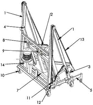
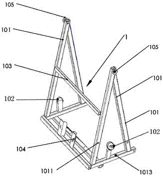
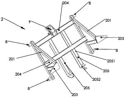
[0028] Such as figure 1 , figure 2 , Image 6 As shown, an electric feeding machine includes a synchronous shaft (7), a guide wheel (8), a lock (9), a driving sprocket (11), a flange (12), a chain (13), a driving device ( 14), the main frame (1), the lifting trolley (2) and the guide rail (4), wherein the main frame (1) includes two side frames (101) and the main frame beam connecting the two side frames (101) (103), side frame (101) is triangular structure, is made up of diagonal brace one (1011), diagonal brace two (1012) and bottom beam (1013), and guide sprocket wheel one (105) is installed on the outside of side frame (101) ) and guide sprocket four (102), and guide sprocket one (105) is at the top position of the side frame (101); there are two guide rails (4), whose cross-section is "凵" type, consisting of inclined rails ( 402) and the flat rail (403) are composed of two parts, the side is "ヘ" type, the guide rail (4) is respectively connected with the diagonal brac...


PUM


Abstract

The invention discloses an electric feeding machine which comprises a synchronizing shaft, a clamping lock, guide rail wheels, driving chain wheels, a flange, chains, a driving device, a main frame, a lifting trolley and guide rails, wherein the main frame is connected with the flange; the synchronizing shaft is supported on the flange; the synchronizing shaft and the driving device are in key connection with the two driving chain wheels on the outer sides of two side frames; a guide chain wheel IV and a guide chain wheel I are further mounted on the outer sides of the two side frames; the guide rail wheel and the clamping lock are mounted on the lifting trolley; the guide rail wheels are assembled in the guide rails; the chains are arranged on two sides of the main frame and are connected with the lifting trolley; a cart is directly lifted by the lifting trolley; and material in a cart hopper is lifted to certain height and dumped to a designated position without a working procedure of traditional material dumping manually or setting up a cart ramp, the transportation procedure is simple, manpower is saved, the efficiency is high, movement is convenient, and feeding construction of building secondary constructional column pouring can be carried out in a narrow floor.

Description

technical field [0001] The invention relates to the field of electric feeders, in particular to a feeder for building secondary structural column pouring machines. Background technique [0002] The feeding machine mainly has two types: the screw auger blade type and the hopper lifting type. Among them, the screw auger blade type feeding is to put the material into the receiving hopper first, and then put the material in the receiving hopper through the thrust generated by the rotation of the auger blade. Transported to the designated position, the hopper lifting type feeding is to put the material into the receiving hopper first, then lift the material to a certain height and pour it to the designated position. But these two methods have obvious limitations when working with carts (including electric carts): [0003] 1. The transportation process is complicated. First, it is necessary to manually pour the materials in the cart into the receiving hopper, and then start the f...

Claims


Application Information

Patent Timeline
IPC IPC(8): B65G17/42B65G17/32B65G23/44
CPCB65G17/32B65G17/42B65G23/44
Inventor 王积政王德宇
Owner 王德宇
Why Eureka
Try Eureka