Push-up system for heavy loads

A heavy-duty, heavy-duty technology, applied in the field of push-up systems for heavy loads, can solve the problems of easy failure, expensive, difficult to replace lifting modules, etc.

Inactive Publication Date: 2017-09-01
MAMMOET HLDG
View PDF1 Cites 0 Cited by
  • Summary
  • Abstract
  • Description
  • Claims
  • Application Information

AI Technical Summary

Problems solved by technology

Both are expensive and prone to failure
Another problem with known push-up systems is that it is difficult to replace a failed lift module

Method used


Image

  • Push-up system for heavy loads
  • Push-up system for heavy loads
  • Push-up system for heavy loads

Examples


Embodiment Construction

[0024] When the same reference numerals are used in the drawings, these reference numerals denote the same parts.

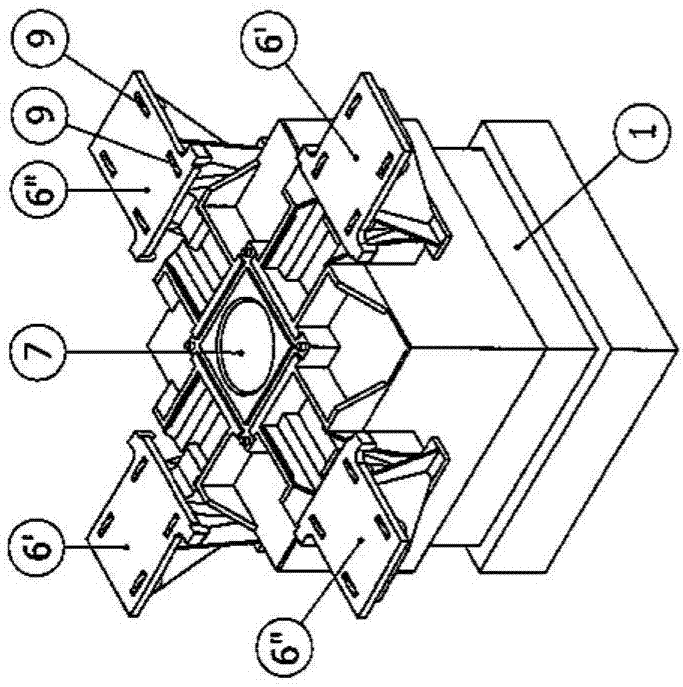
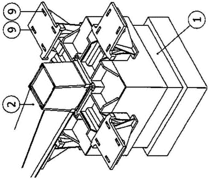
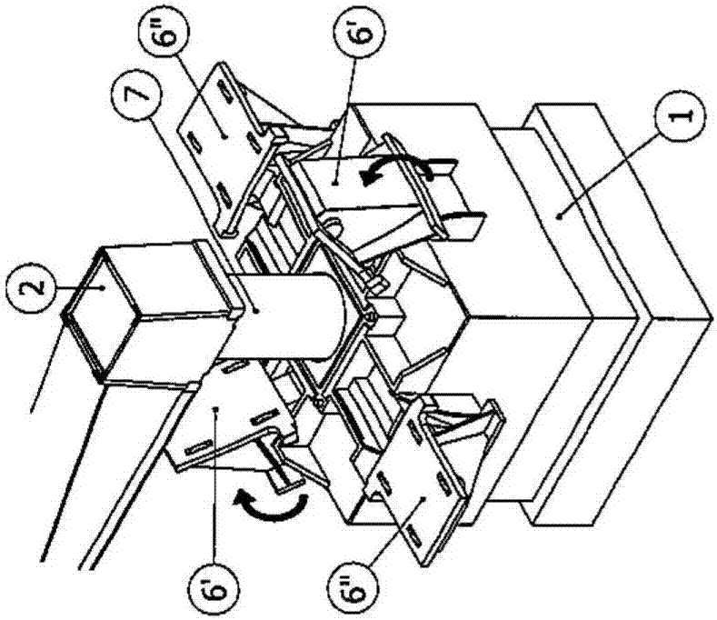
[0025] first reference Figure 11 and 12 , the push-up system of the present invention is shown in a rectangular configuration. exist Figure 11 Four lifting modules 1 are used in the Figure 12 Six lifting modules 1 are used in the system. In a manner known per se from Dutch patent 1037817, for raising or lowering the load, the support beams 2 are arranged staggeredly in or removed from the stack of load-carrying support beams 2, wherein the support beams 2 are in a first direction and are disposed on top of each other in a second direction transverse to the first direction. For example, a support beam 2 arranged in a first direction is supported or removed using a roller track 4 shown on the left side of the figure, while a support beam 2 arranged in a second direction is supported or removed using a roller track 4 shown on the right side of the figure 4 ...


PUM


Abstract

The invention provides a push-up system for heavy loads comprising multiple lift modules (1) that are usable to collectively support and raise a load, wherein each lift module (1) is capable to receive a support beam (2, 2') on top of it, and wherein the support beam (2, 2') is placeable on top of the lift module (1) in at least one of a first direction and a second direction which traverses the first direction, and wherein each lift module (1) is equipped with supports (6, 6', 6'') for the support beam (2, 2'), wherein the supports (6, 6', 6'') are swivably mounted at an upper end of the lift module (1) and arranged to be displaceable between a first position wherein the support's guiding surface is horizontal and a second position wherein the supports are swiveled away from the first position so as to arrange that the support's guiding surface is perpendicular with said upper face of the lift module (1).

Description

technical field [0001] The present invention relates to a push-up system for heavy loads comprising a plurality of lifting modules that together support and raise or lower the load, wherein each lifting module is capable of receiving a support beam at its top end, wherein the support beams can Placed on top of the lifting modules in one of a first direction and a second direction transverse to the first direction, and wherein each lifting module is equipped with a bracket for guiding a support beam. The support beams are arranged in a stack on top of each other in staggered directions (i.e. said first and second directions) such that raising or lowering by adding or removing support beams in the stack is supported by the highest The load supported by the beam. The two directions may be completely perpendicular to each other, or at an angle other than 90°. Background technique [0002] Dutch patent 1037817, the content of which is incorporated herein by reference, discloses...

Claims


Application Information

Patent Timeline
Patent Type & Authority Applications(China)
IPC IPC(8): B66F7/20B66F3/25
CPCB66F3/247B66F3/25B66F7/20B66F3/46B66F1/00B65G13/00
Inventor 韦塞尔·赫尔门斯安东·阿德里安·约阿希姆·范登布鲁克
Owner MAMMOET HLDG
Why Eureka
Try Eureka