
Bridge telescopic device with high applicability

A telescoping device and applicability technology, applied in bridges, bridge construction, bridge parts, etc., can solve the problems of low telescoping performance, large gap between two beam ends, and vehicles cannot pass smoothly, etc., and achieve strong telescoping performance, high performance, Effect of improving smooth driving performance

Pending Publication Date: 2017-09-01
浙江秦山橡胶工程股份有限公司
View PDF12 Cites 5 Cited by
  • Summary
  • Abstract
  • Description
  • Claims
  • Application Information

AI Technical Summary

Problems solved by technology

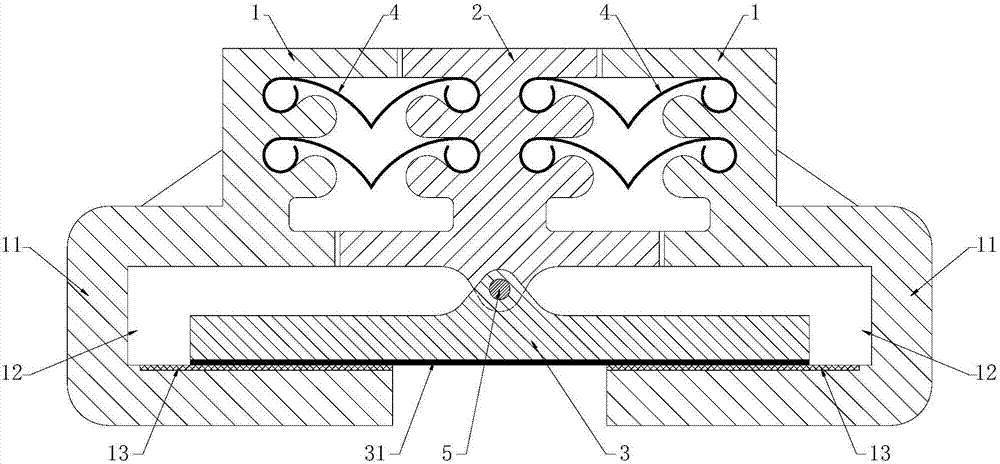
[0006] The purpose of the present invention is to overcome the shortcomings of the above-mentioned prior art and provide a bridge expansion device with strong applicability, which aims to solve the problem that the expansion performance of the expansion device in the prior art is low, which easily leads to a large gap between the ends of the two beams , leading to the technical problem that the vehicle cannot smoothly pass through the joint of the two beam ends

Method used


Image

  • Bridge telescopic device with high applicability
  • Bridge telescopic device with high applicability
  • Bridge telescopic device with high applicability

Examples


Embodiment 1

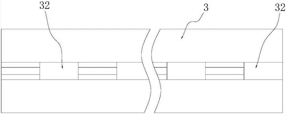
[0031] Embodiment one, refer to image 3 , the upper connecting portion 21 and the lower connecting portion 32 are arranged alternately.

Embodiment 2

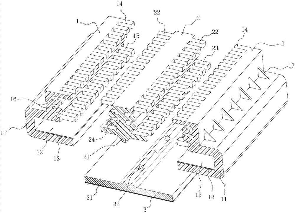
[0032] Embodiment two, refer to Figure 4 , the lower connecting portion 32 is located at the front and rear ends of the sliding beam 3, the upper connecting portion 21 is located between the two lower connecting portions 32, and each lower connecting portion 32 and the upper connecting portion 21 pass through the reinforcing shaft 5 connect.

[0033] Beneficial effects of the present invention: Compared with the prior art, the present invention provides a bridge telescopic device with strong applicability, which has a reasonable structure, adopts the structural form of two side beam steels 1 and the middle beam steel 2, and increases the bridge The telescopic range of the telescopic device has strong telescopic performance, and the middle beam steel 2 is meshed with the side beam steel 1 on both sides, which ensures the large displacement between the middle beam steel 2 and the side beam steel 1 The bottom can still be overlapped, can transition smoothly, and improve the smo...


PUM


Abstract

The invention discloses a bridge telescopic device with high applicability. The bridge telescopic device comprises two pieces of boundary beam profile steel, intermediate beam profile steel arranged between the two pieces of boundary beam profile steel, a sliding crossbeam and water stopping adhesive tape. The two pieces of boundary beam profile steel are symmetrically arranged on the left side and the right side of the intermediate beam profile steel. The intermediate beam profile steel and the two pieces of boundary beam profile steel are connected in a meshing mode through comb teeth. The bottoms of the two pieces of boundary beam profile steel are provided with sliding boxes. Each sliding box is internally provided with a sliding cavity. The left and right sides of the sliding crossbeam are erected in the sliding cavity of the left boundary beam profile steel and the sliding cavity of the right boundary beam profile steel. The upper end of the sliding crossbeam are movably hinged to the bottom of the intermediate beam profile steel. The water stopping adhesive tape is connected between the intermediate beam profile steel and the left boundary beam profile steel and between the intermediate beam profile steel and the right boundary beam profile steel. According to the bridge telescopic device with the high applicability, by adopting the structure mode that the intermediate beam profile steel is arranged between the two pieces of boundary beam profile steel, the device has high telescopic performance, the large displacement and inclination displacement can be met, and the smooth running performance of the vehicle is improved.

Description

[0001] 【Technical field】 [0002] The invention relates to the technical field of expansion devices for highway bridges, in particular to a bridge expansion device with strong applicability. [0003] 【Background technique】 [0004] In order to meet the deformation requirements of the bridge deck, telescopic devices are usually installed between the two girder ends, between the girder end and the abutment, or at the hinged position of the bridge. The bridge expansion device is an important part of the bridge deck structure. Its quality directly affects the driving performance of the vehicle and the service life of the bridge. Its main function is to adapt to the beam body due to temperature difference, concrete drying shrinkage, and prestressed concrete creep shrinkage. And the displacement caused by the action of load, etc., plays the role of sealing the seam to protect the structure under the bridge. The current telescopic device has low telescoping performance, which easily ...

Claims


Application Information

Patent Timeline
Patent Type & Authority Applications(China)
IPC IPC(8): E01D19/06
CPCE01D19/065
Inventor 王建芬
Owner 浙江秦山橡胶工程股份有限公司
Learn More