Bridge illuminating lamp device

A lighting and bridge technology, applied to lighting devices, fixed lighting devices, components of lighting devices, etc., can solve problems such as electric shock accidents, hidden safety hazards, cumbersome and complicated operations, etc., to avoid electric shock accidents, reduce potential safety hazards, The effect of avoiding electric shock

Inactive Publication Date: 2017-09-01
江苏承煦电气集团有限公司
View PDF4 Cites 3 Cited by
  • Summary
  • Abstract
  • Description
  • Claims
  • Application Information

AI Technical Summary

Problems solved by technology

[0002] In bridge construction, some lighting lamps are generally installed for bridge night lighting. However, these lighting lamps are generally fixed and connected by fastening bolts. , the operation is cumbersome and complicated, which greatly reduces the efficiency of maintenance. At the same time, the lamp holders of the existing bridge lighting lamps are generally connected to the mains. contact with conductive parts, it is very easy to cause electric shock accidents, and there is a great potential safety hazard

Method used


Image

  • Bridge illuminating lamp device
  • Bridge illuminating lamp device
  • Bridge illuminating lamp device

Examples


Embodiment Construction

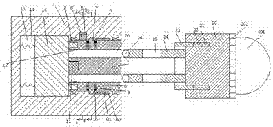
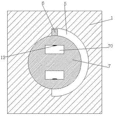
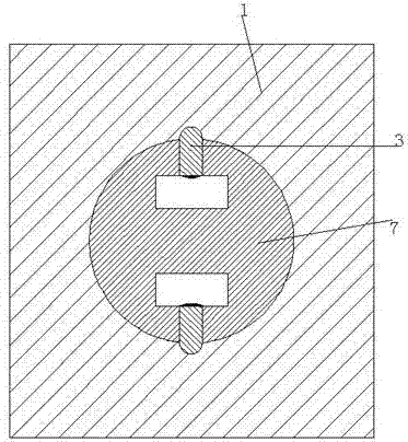
[0029] Combine below Figure 1-11 The present invention will be described in detail.

[0030] refer to Figure 1-11 , a bridge lighting device according to an embodiment of the present invention, comprising a lamp holder 1 and a lamp holder 20 used in conjunction with the lamp holder, the lamp holder 20 is provided with a first annular groove 21 with a notch facing the left end, A shell 23 is slidably installed in the first ring joint groove 21, and the left end surface of the lamp cap 20 is equipped with inserting posts 24 located in the shell 23, and the inserting posts 24 are provided with upper and lower Through the perforation 25, the right end of the lamp holder 20 is fixed with an LED bulb 201, and the end of the LED bulb 201 close to the lamp holder 20 is fixed with a lamp housing 202, through which the lamp housing 202 can effectively prevent the The LED light bulb 201 is damaged due to excessive force during the installation process; the lamp holder 1 is provided w...


PUM


Abstract

A bridge illuminating lamp device comprises a lamp seat and a lamp holder matched with the lamp seat in use. A first annularly-connected groove with a groove port facing the left end is formed in the lamp holder; a shell sleeve is mounted in the first annularly-connected groove in a slidably connecting mode; inserting columns located in the shell sleeve are mounted on the left end face of the lamp holder in an up-down opposite mode; vertically-through penetrating holes are formed in the inserting columns; a middle groove is formed in the lamp seat; a transferring part is mounted in the middle groove in a transferring mode; inserting grooves matched with the inserting columns are formed in the transferring part in an up-down opposite mode; first electric connecting pieces are fixedly mounted on the left sides of the inner walls of the inserting grooves; first inserting holes and second inserting holes are further formed in the left end face of the transferring part, wherein the first inserting holes are formed in an up-down opposite mode, and hole ports of the first inserting holes face leftwards, and the second inserting holes are formed in an front-rear opposite mode; a square groove with an groove port facing leftwards is formed in the middle of the left end face of the transferring part; second electric connecting pieces are fixedly mounted on the upper and lower end walls of the square groove; a sliding connecting groove is formed in the position, located at the left end of the middle groove, of the lamp seat; and a sliding connecting block is mounted in the sliding connecting groove in a left-right sliding connecting mode.

Description

technical field [0001] The invention relates to the technical field of bridge lighting, in particular to a bridge lighting device. Background technique [0002] In bridge construction, some lighting lamps are generally installed for bridge night lighting. However, these lighting lamps are generally fixed and connected by fastening bolts. , the operation is cumbersome and complicated, which greatly reduces the efficiency of maintenance. At the same time, the lamp holders of the existing bridge lighting lamps are generally connected to the mains. Contact with the conductive parts of the battery can easily cause electric shock accidents, and there is a great potential safety hazard. Contents of the invention [0003] The object of the present invention is to provide a bridge lighting device for overcoming the above-mentioned defects in the prior art. [0004] A bridge lighting device according to the present invention, comprising a lamp holder and a lamp cap used in conjunc...

Claims


Application Information

Patent Timeline
Patent Type & Authority Applications(China)
IPC IPC(8): F21S8/00F21V17/16F21V19/04F21Y115/10
CPCF21S8/00F21V17/166F21Y2115/10
Inventor 何华勇
Owner 江苏承煦电气集团有限公司
Why Eureka
Try Eureka