Linear motor

A technology of linear motors and coils, which is applied in the direction of electric components, linear motion bearings, electrical components, etc., and can solve the problems of linear motor size increase and rod stroke limitation

Active Publication Date: 2008-08-27
THK CO LTD
View PDF2 Cites 8 Cited by
  • Summary
  • Abstract
  • Description
  • Claims
  • Application Information

AI Technical Summary

Problems solved by technology

However, in this method, the linear guide provided between the base and the rod not only increases the size of the linear motor, but also restricts the stroke of the rod.

Method used


Image

  • Linear motor
  • Linear motor
  • Linear motor

Examples


Embodiment Construction

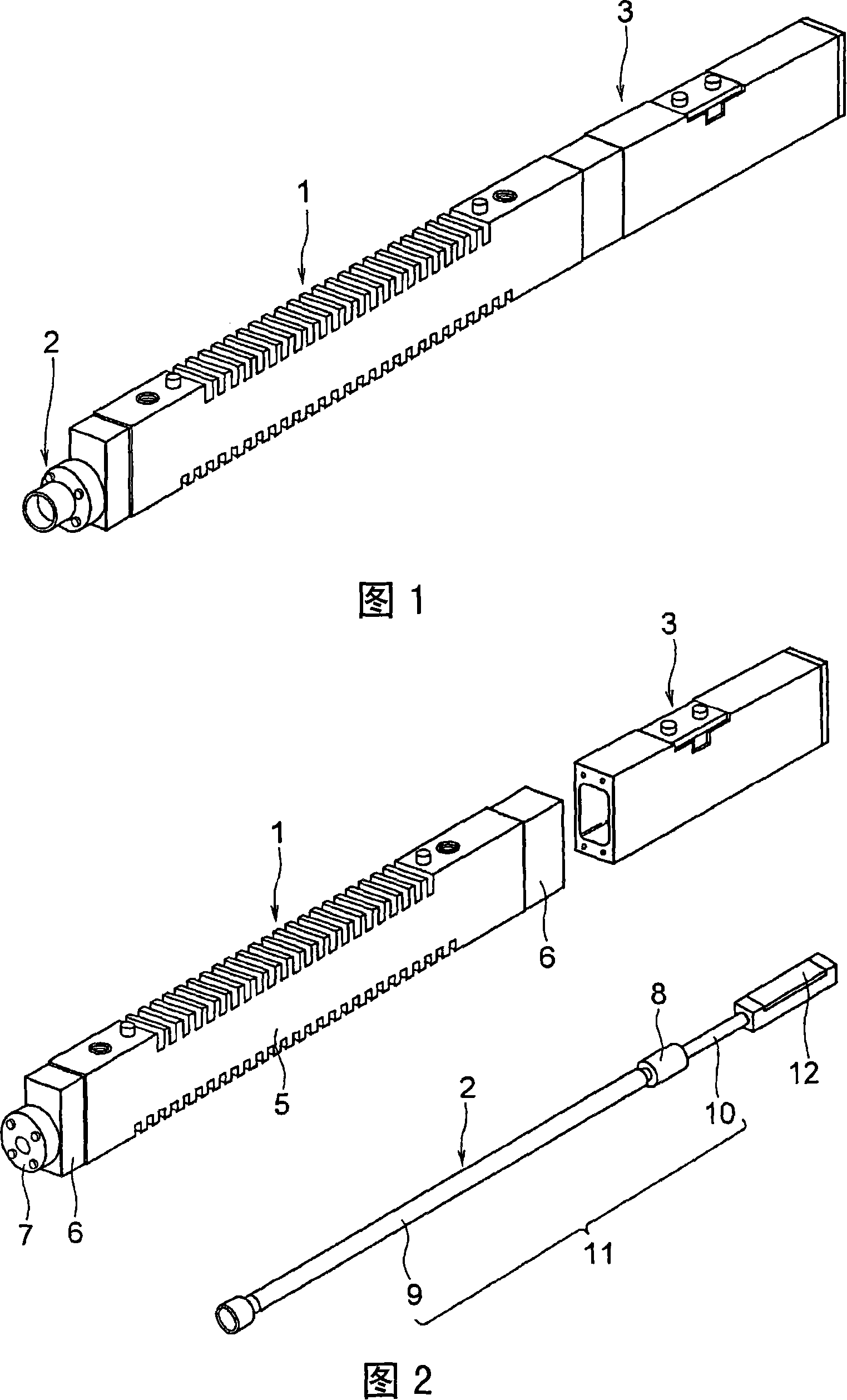
[0043] Embodiments of the present invention will be described in detail based on the drawings. FIG. 1 is an external perspective view showing a linear motor according to one embodiment of the present invention. The linear motor of this embodiment is a one-axis actuator, and is used to convey a moving body such as an electronic component in one axis direction. More specifically, for example, it is used to mount a chip-shaped electronic component on a drive shaft of a chip mount at a predetermined position. A rod part 2 capable of advancing and retreating is incorporated into a long and thin rectangular parallelepiped motor body part 1 . The speed and moving distance of the rod part 2 are detected by the detection part 3 installed at the rear end of the motor body part 1 .

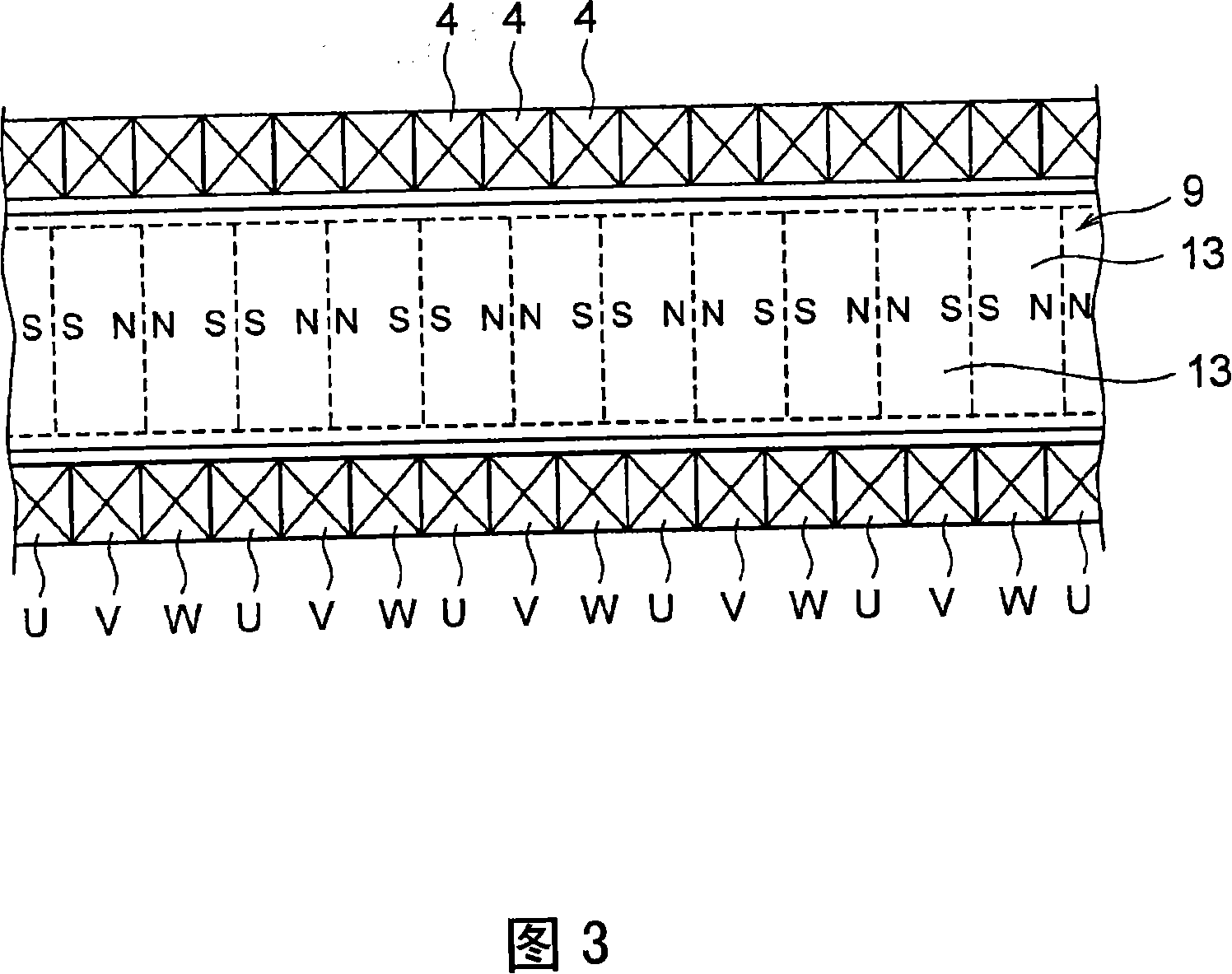
[0044] FIG. 2 shows a state in which the linear motor is disassembled into a motor body 1 , a rod body 2 , and a detection unit 3 . First, the schematic configuration of these parts will be described.

...


PUM


Abstract

Provided is a compact linear motor wherein rotation of a rod, which linearly moves relatively to a coil, can be limited. The linear motor is provided with the rod (11) having a magnet (13); a coil (4) surrounding the rod (11); and a housing (5) covering the coil (4). The linear motor permits the rod (11) to linearly move relatively to the coil (4) by the magnetic field of the magnet (13) and a current flowing in the coil (4). On the outer circumference of the rod (11), a spline groove (10a) extending in an axis line direction of the rod (11) is formed. The housing (5) is provided with a spline nut (8) which limits rotation of the rod (11) in the axis line direction by being fitted in the spline groove (10a).

Description

technical field [0001] The present invention relates to a linear motor that obtains thrust for linear motion by utilizing the magnetic field of a magnet and the current flowing through a coil, and more particularly relates to a rod-shaped linear motor in which a rod with a magnet is inserted into a plurality of stacked coils. electric motor. Background technique [0002] A linear motor is a motor in which the stator side and the rotor side of a rotary motor are stretched linearly, and electric energy is converted into thrust for linear motion. A linear motor that obtains linear thrust is used as a one-axis actuator that linearly moves a moving body. [0003] Linear motors are classified by shape into rod type and flat type. A rod-type linear motor is formed by laminating a plurality of cylindrical coils, and inserting a rod having a magnet into a hole of the laminated coil. For example, when a three-phase current with a phase difference of 120° flows through a plurality o...

Claims


Application Information

Patent Timeline
Patent Type & Authority Applications(China)
IPC IPC(8): H02K41/02H02K41/03
CPCH02K41/03F16C29/0685H02K7/08
Inventor 浅生利之山中修平
Owner THK CO LTD
Why Eureka
Try Eureka