Segmentation method for brittle substrates

A brittle substrate, continuous technology, used in glass cutting devices, fine work devices, work accessories, etc., to ensure the life and reduce the load.

Active Publication Date: 2021-09-24
MITSUBOSHI DIAMOND IND CO LTD
View PDF9 Cites 0 Cited by
  • Summary
  • Abstract
  • Description
  • Claims
  • Application Information

AI Technical Summary

Problems solved by technology

As shown in the technology of this patent document 1, in the conventional typical technology, the crack line is formed simultaneously with the formation of the scribe line.

Method used


Image

  • Segmentation method for brittle substrates
  • Segmentation method for brittle substrates
  • Segmentation method for brittle substrates

Examples


Embodiment and comparative example 3

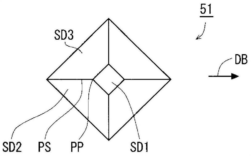
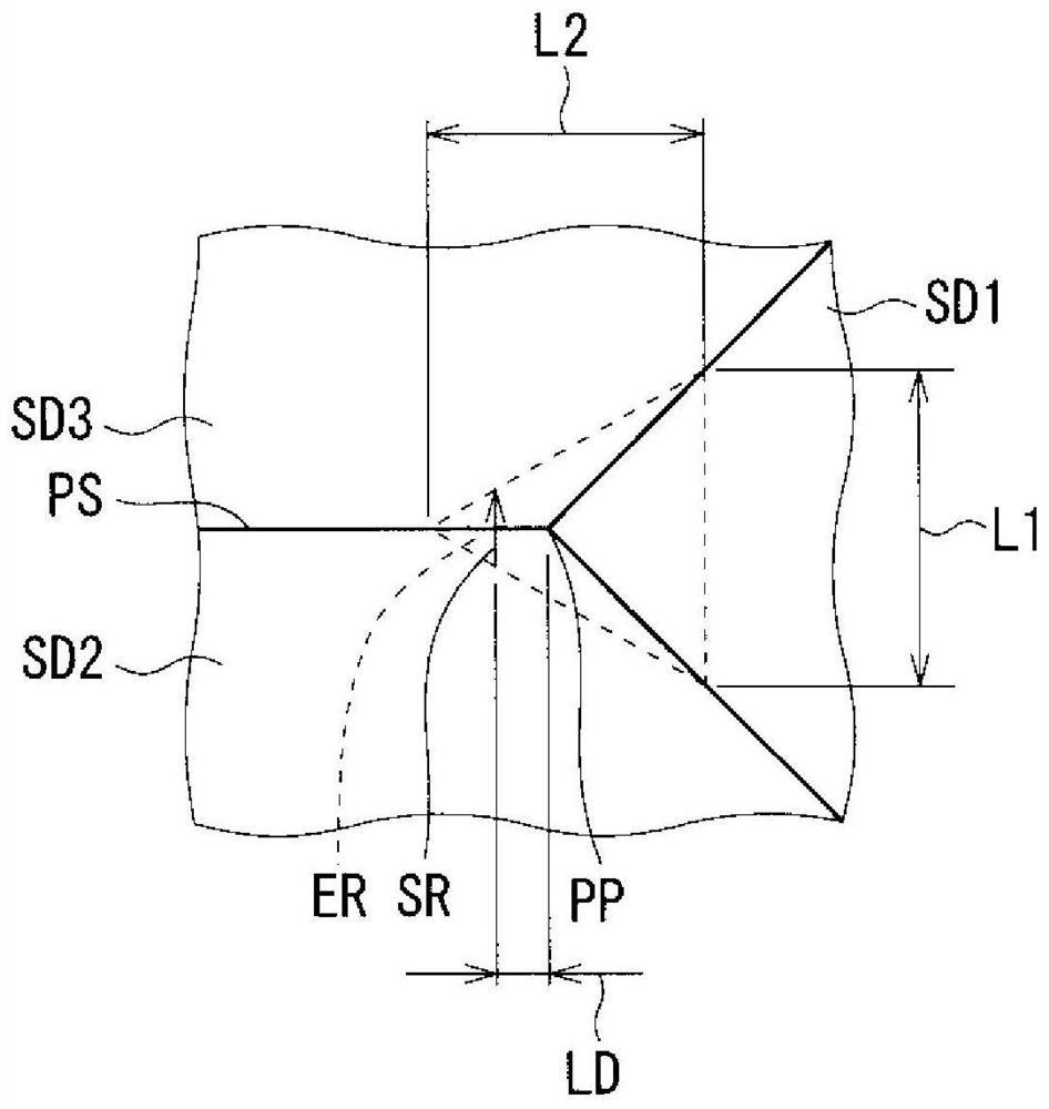
[0085] Figure 11 It is a side view which schematically shows the divided shape of the glass substrate 4 in the example of this embodiment. Figure 12 It is a side view schematically showing the divided shape of the glass substrate 4 of Comparative Example 3. FIG. The thickness of the divided glass substrate 4 was set to 0.1 mm. The surface obtained by dividing the glass substrate 4 (hereinafter also referred to as "divided surface") and Figure 11 as well as Figure 12 Corresponding to the right in , the height difference of the split planes is emphatically depicted based on the surface profile obtained by laser microscopy. The edge line PS ( image 3 ) is a ridge line without chamfering in the example, and a chamfered line in Comparative Example 3. The radius of curvature of the ridge line PS is 0.6 μm in the example, and 3.9 μm in the third comparative example.

[0086] Compared with the dividing surface of Comparative Example 3, the dividing surface of the example ha...


PUM

PropertyMeasurementUnit
radiusaaaaaaaaaa
sizeaaaaaaaaaa
sizeaaaaaaaaaa

Abstract

A method for dividing a brittle substrate that facilitates the preparation of the tip and ensures sufficient life of the tip when the tip having the vertex where three surfaces meet slides with its ridge line as the rear side. Prepare the tip with a first face (SD1), a second face (SD2) and a third face (SD3), the second face (SD2) is adjacent to the first face (SD1), and the third face (SD3) A ridgeline is formed by being adjacent to the second surface (SD2), and an apex is formed by being adjacent to each of the first surface (SD1) and the second surface (SD2). The ridgeline is a ridgeline that has not been chamfered. On one surface (SF1) of the brittle substrate (4), the tip of the knife (51) slides toward the direction from the ridge line (PS) toward the first surface (SD1), thereby A trench line (TL) having a groove shape is formed in a crack-free state. Crack lines (CL) are formed along the trench lines (TL). The brittle substrate (4) is divided along the crack line (CL).

Description

technical field [0001] The present invention relates to a method for dividing a brittle substrate, in particular to a method for dividing a brittle substrate using sliding of a knife tip. Background technique [0002] In the manufacture of electrical devices such as flat panel display panels or solar cell panels, it is often necessary to separate brittle substrates. In a typical segmentation method, first, a crack line is formed on a brittle substrate. In this specification, a "crack line" refers to a line in which a crack locally developed in the thickness direction of a brittle substrate extends linearly on the surface of the brittle substrate. Next, a so-called breaking step is performed. Specifically, by applying stress to the brittle substrate, the crack of the crack line is completely developed in the thickness direction. Thereby, the brittle substrate can be divided along the crack line. [0003] According to Patent Document 1, some kind of depression occurs on th...

Claims


Application Information

Patent Timeline
Patent Type & Authority Patents(China)
IPC IPC(8): B28D1/22B28D5/00C03B33/10
CPCB28D1/225B28D5/0011C03B33/105B28D5/04B28D7/00H01L21/76
Inventor 曾山浩
Owner MITSUBOSHI DIAMOND IND CO LTD
Why Eureka
Try Eureka