Hand-held self-rotated reinforcing steel bar hook

A self-rotating, hand-held technology, which is applied in the direction of construction, building structure, and building material processing, can solve the problems of low work efficiency and difficult operation, and achieve the effect of high work efficiency and simple operation

Active Publication Date: 2017-09-05
池仁淼
View PDF9 Cites 3 Cited by
  • Summary
  • Abstract
  • Description
  • Claims
  • Application Information

AI Technical Summary

Problems solved by technology

[0004] The purpose of the present invention is to provide a hand-held self-rotating steel bar hook, which solves the problems that the previous steel bar hook needs to be used by shaking the wrist, which is difficult to operate and low in work efficiency, and realizes hand-held rotation. The invention is easy to operate and high in work efficiency.

Method used


Image

  • Hand-held self-rotated reinforcing steel bar hook
  • Hand-held self-rotated reinforcing steel bar hook
  • Hand-held self-rotated reinforcing steel bar hook

Examples


specific Embodiment approach 1

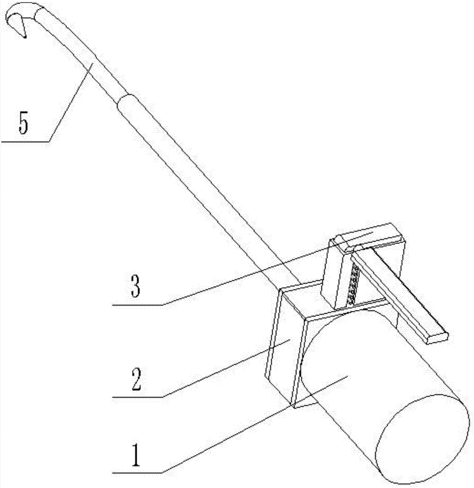
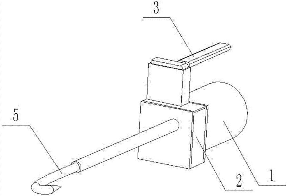
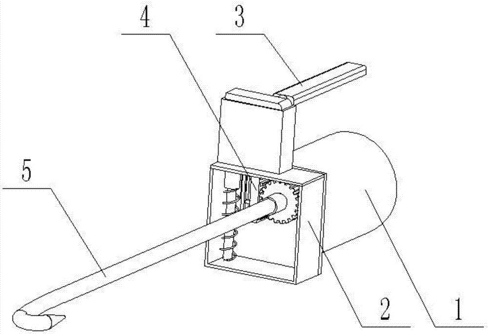
[0053] Combine below figure 1 , 2 , 3, 4, 5, 6, 7, 8, 9, 10, 11, 12, 13, 14, 15 illustrate this embodiment, a hand-held self-rotating steel bar hook, including a handle 1, a device box 2, a push The pressing device 3, the rack device 4, and the rotating device 5 are characterized in that: the front end of the handle 1 is provided with a device box 2, the upper end of the device box 2 is provided with a pushing device 3, and the inside of the device box 2 is provided with a rack device 4 and a rotating device 5. The rotating device 5 is arranged at the left end of the rack device 4 .

specific Embodiment approach 2

[0055] Combine below figure 1 , 2 , 3, 4, 5, 6, 7, 8, 9, 10, 11, 12, 13, 14, 15 illustrate this embodiment, the device box 2 includes a rear end cover 2-1, an upper end cover 2- 2. Plug box 2-3, inverted door-shaped frame 2-4, front cover 2-5, bushing Ⅰ 2-6, rear cover 2-1 front end welded and connected upper cover 2-2, The right end of the upper end cover plate 2-2 is welded and connected to the plug box 2-3, the front end of the rear end cover plate 2-1, the lower end of the upper end cover plate 2-2 is welded and connected to the inverted door-shaped frame 2-4, and the upper end cover plate 2- 2. The front end, the inverted door-shaped frame 2-4 is welded to the front end cover plate 2-5, the rear end cover plate 2-1, the upper end cover plate 2-2, the inverted door-shaped frame 2-4 and the front end cover plate 2-5 constitutes an internal hollow cuboid structure, and the front end of the front cover plate 2-5 is welded to connect the casing I2-6;

[0056] The rear end c...

specific Embodiment approach 3

[0064] Combine below figure 1 , 2 , 3, 4, 5, 6, 7, 8, 9, 10, 11, 12, 13, 14, 15 illustrate this embodiment, the pushing device 3 includes a pressing rod 3-1, a connecting shaft 3-2, Pressing plate 3-3, down-pressing connecting rod 3-4, positioning attachment plate 3-5, casing II 3-6, pressing rod 3-1 is welded and connected to connecting shaft 3-2 at the front end, connecting shaft 3-2 is welded and connected to pressing plate 3 at the front end -3, the right end of the lower end of the pressing plate 3-3 is welded and connected to the sleeve II 3-6, the left end of the lower end of the pressing plate 3-3 is welded and connected to the lower pressing connecting rod 3-4, the right end of the lower pressing connecting rod 3-4 is welded and connected to the positioning attachment plate 3- 5;

[0065] Described pressing down connecting rod 3-4 comprises first connecting rod 3-4-1, second connecting rod 3-4-2, upper positioning shaft 3-4-3, lower positioning shaft 3-4-4, the firs...


PUM


Abstract

The invention relates to a building tool, and concretely relates to a hand-held self-rotated reinforcing steel bar hook, which solves the problems that a former reinforcing steel bar hook needs to be used by shaking a wrist, and is big in operation difficulty and low in work efficiency, and realizes hand-held rotation. The hand-held self-rotated reinforcing steel bar hook provided by the invention is simple to operate and high in work efficiency, and comprises a handle, a device box, a pushing and pressing device, a rack device and a rotary device. The hand-held self-rotated reinforcing steel bar hook is characterized in that the device box is arranged at the front end of the handle; the pushing and pressing device is arranged at the upper end of the device box; the rack device and the rotary device are arranged in the device box. The rack device comprises a rack, an upper positioning block and a lower positioning block; the upper positioning block is connected to the upper end of the right end face of the rack in a welding way; the lower positioning block is connected to the lower end of the right end face of the rack in a welding way; a first oblique sliding chute is arranged at the side end face of the upper positioning block, penetrates through the front end face and the rear end face of the upper positioning block, and is arranged along a direction from the left upper corner to the right upper corner of the upper positioning block.

Description

technical field [0001] The invention relates to a construction tool, in particular to a hand-held self-rotating steel bar hook. Background technique [0002] Steel bar hook is a common tool for binding steel bars on construction sites, and is often used for fastening work when metal binding wires are used to bind steel bars. Existing steel bar hooks have various materials and models, but most of them are similar in structure. They are composed of handles, hook bodies and other components. [0003] For example, the patent application number is a new type of steel hook CN201420187671.9. The steel hook includes a handle, a hook body and a fastener; the handle is a tubular structure with two ends open, and its external front end is tapered. The inner diameter of the handle is smaller than the inner diameter of the end, and the intersection of two different inner diameters forms a ring-shaped card platform, and the inner wall of the end of the handle is provided with internal th...

Claims


Application Information

Patent Timeline
Patent Type & Authority Applications(China)
IPC IPC(8): E04G21/12
CPCE04G21/123
Inventor 池仁淼
Owner 池仁淼
Why Eureka
Try Eureka