Rotating joint

A technology of rotary joints and outer shells, which is applied in the direction of pipe components, etc., can solve the problems of large fitting clearance of rotary joints, shortened service life of rotary joints, and non-rotation of rotary joints, etc., and achieves the effect of cost reduction and good sealing

Inactive Publication Date: 2017-09-05
GUANGDONG UNIV OF TECH
View PDF7 Cites 1 Cited by
  • Summary
  • Abstract
  • Description
  • Claims
  • Application Information

AI Technical Summary

Problems solved by technology

[0004] However, the rotary joint in the prior art has the following disadvantages: when the weight of the high-pressure rotary joint rotor is too large, the low-quality bearing will be crushed by the gravity of the rotor, causing the rotary joint to not rotate, and poor bearings cannot guarantee the concentricity of the rotor , it will make the rotary joint fit too large, resulting in a slight swing when rotating, which will affect the service life of the rotary joint; due to long-term use, the sealing element will be damaged and the lubrication effect will be affected; when the airport spindle speed is too high and The stator of the rotary joint is in contact with the rotor for a long time, and the service life of the rotary joint will be severely shortened

Method used


Image

  • Rotating joint

Examples


Embodiment Construction

[0023] The core of the present invention is to provide a rotary joint, which effectively realizes the problem of unlimited dry running without medium pressure.

[0024] The following will clearly and completely describe the technical solutions in the embodiments of the present invention with reference to the accompanying drawings in the embodiments of the present invention. Obviously, the described embodiments are only some, not all, embodiments of the present invention. Based on the embodiments of the present invention, all other embodiments obtained by persons of ordinary skill in the art without making creative efforts belong to the protection scope of the present invention.

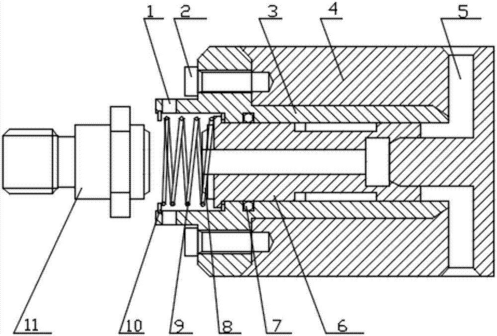
[0025] Please refer to figure 1 , figure 1 It is a structural schematic diagram of a rotary joint provided in a specific embodiment of the present invention.

[0026] In a specific embodiment, the rotary joint provided by the present invention is installed in the machine tool body 4, and includes a ...


PUM


Abstract

The invention discloses a rotating joint installed on a machine tool body (4). The rotating joint comprises a joint outer shell (3) and a sealing mechanism, wherein the joint outer shell (3) is arranged in the machine tool body (4) in a sleeved mode, and the sealing mechanism is arranged in the joint outer shell (3). The end of the joint outer shell (3) is provided with a connection hole (1) connected with a main shaft. The sealing mechanism comprises a hollow joint core shaft (6), a disc-shaped sealing ring (8) and a spring (9), wherein the joint core shaft (6) is inserted into the joint outer shell (3), the disc-shaped sealing ring (8) is installed on the end face of a shaft head of the outer end of the joint core shaft (6), one end of the spring (9) is connected with the disc-shaped sealing ring (8), the other end of the spring (9) is clamped to the tail end of the joint outer shell (3), the inner end of the joint core shaft (6) can be connected with the machine tool body (4), and a cavity between the machine tool body (4) and the rotating joint can communicate with a through hole in the joint core shaft (6). Unlimited dry operation without medium pressure is effectively achieved through the rotating joint.

Description

technical field [0001] The invention relates to the technical field of machine tools, in particular to a rotary joint. Background technique [0002] Hydraulic leakage not only causes waste of oil materials, but also causes shutdown losses, environmental pollution, low system efficiency, and fire hazards. According to foreign data, before the implementation of leak prevention and control, the annual loss of hydraulic system leakage in the UK was as high as 180 million US dollars. According to incomplete statistics from American magazines, the leakage of hydraulic systems in factories across the United States costs 60 million U.S. dollars every year. According to the investigation report, it is found that the main leakage points of the hydraulic system are concentrated at the pipe joints, especially in the moving parts such as rotation. The role of the rotary joint is to input the liquid from the side of the pipeline into the rotating or reciprocating equipment, and then dis...

Claims


Application Information

Patent Timeline
Patent Type & Authority Applications(China)
IPC IPC(8): F16L39/06
CPCF16L39/06
Inventor 郭钟宁刘宇迅刘莉
Owner GUANGDONG UNIV OF TECH
Why Eureka
Try Eureka