Pressure test machine loading device
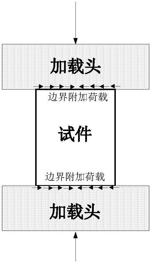
A technology of loading device and pressure test, applied in measuring device, using stable tension/pressure test material strength, instrument and other directions, can solve the problem that the force of the test piece is different from the expected situation, affecting the accuracy of test results, etc. The effect of reducing test error and improving accuracy
- Summary
- Abstract
- Description
- Claims
- Application Information
AI Technical Summary
Problems solved by technology
Method used
Image
Examples
Embodiment 1
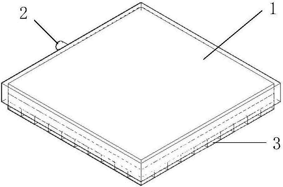
[0033] Such as figure 2 As shown, a loading device for a pressure testing machine includes a casing 1 and a loading part, the loading part is installed in the casing 1, and the connection part forms a seal. A pressure chamber is formed between the housing 1 and the loading part, and a pressure tube 2 is provided on the side of the housing 1. One end of the pressure tube 2 communicates with the pressure chamber, and the other end is connected to an external pressure pipeline. The pressurized medium enters from the pressurization tube 2 In the pressure chamber, pressure is applied to the loading part.
[0034] The loading part includes a fixed chassis and a plurality of loading blocks 3 . The loading blocks 3 are arranged in a criss-cross pattern on the fixed chassis, and there are gaps between adjacent loading blocks 3 . The pressure medium in the pressure chamber pressurizes each loading block 3 independently, and the loading blocks 3 operate independently of each other.
...
Embodiment 2
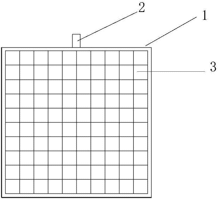
[0037] Such as image 3 with Figure 4 As shown, a loading device for a pressure testing machine includes a casing 1 and a loading part, the loading part is installed in the casing 1, and the connection part forms a seal. The loading part includes a fixed chassis 5 and one hundred loading blocks 3 , the loading blocks 3 are arranged on the fixed chassis 5 in the form of 10×10, and there are gaps between adjacent loading blocks 3 .
[0038] A pressure chamber is formed between the casing 1 and the fixed chassis 5, and a pressurized pipe 2 is provided on the side of the casing 1. One end of the pressurized pipe 2 communicates with the pressure chamber, and the other end is connected with a hydraulic oil pipeline. The pressure chamber is filled with hydraulic oil. For pressurization, the loading pressure can be adjusted accurately.
[0039] Such as Figure 5 with Image 6 As shown, each loading block 3 is connected to the fixed chassis 5 through a piston connecting piece, and...
Embodiment 3
[0041] Such as Figure 7 As shown, the difference between this embodiment and the above-mentioned embodiment is that the piston connector includes a piston 4 and a joint 7, and a connecting rod is arranged between the piston 4 and the joint 7. The middle part of one side of the loading block 3 is provided with a connection groove 8, and the joint 7 is installed in the connection groove 8 to form a connection. There is a gap between the joint 7 and the connecting groove 8, so that the loading block 3 has a certain movable space. At the same time, the joint 7 is spherical, and the connecting groove 8 is a spherical groove, so that the loading block 3 has a certain rotation space. Each loading block 3 can move independently on the contact surface of the test piece, so that the surface of the loading part and the surface of the test piece can be bonded together, and pressure can be effectively exerted on each point of the test piece to reduce the test error.
[0042] In addition...
PUM
 Abstract
Description
Claims
Application Information
 - R&D
- Intellectual Property
- Life Sciences
- Materials
- Tech Scout
- Unparalleled Data Quality
- Higher Quality Content
- 60% Fewer Hallucinations
Browse by: Latest US Patents, China's latest patents, Technical Efficacy Thesaurus, Application Domain, Technology Topic, Popular Technical Reports.
© 2025 PatSnap. All rights reserved.Legal|Privacy policy|Modern Slavery Act Transparency Statement|Sitemap|About US| Contact US: help@patsnap.com


