
Vehicle-mounted camera automatic calibration method based on lane line vanishing points

An automatic calibration and lane line technology, applied in the field of automotive image processing, can solve the problems of harsh calibration conditions, inconvenient operation, and large amount of calculation, and achieve the effect of fast calibration time, simple and convenient operation, and small amount of calculation.

Active Publication Date: 2017-09-05
常州智行科技有限公司
View PDF3 Cites 22 Cited by
  • Summary
  • Abstract
  • Description
  • Claims
  • Application Information

AI Technical Summary

Problems solved by technology

[0003] Some existing calibration methods are to place tools of specific shape and size in front of the vehicle or on the road, and obtain the calibration matrix after image processing. Such methods need to use tools all the time during the calibration process, and require manual participation, and the operation is not easy. convenient
Some extract the inclination information of the camera through the GPS chip inside the camera, and obtain the calibration matrix through a series of complex calculations. This kind of method is cumbersome in actual implementation, with a large amount of calculation and harsh calibration conditions.

Method used


Image

  • Vehicle-mounted camera automatic calibration method based on lane line vanishing points
  • Vehicle-mounted camera automatic calibration method based on lane line vanishing points
  • Vehicle-mounted camera automatic calibration method based on lane line vanishing points

Examples


Embodiment Construction

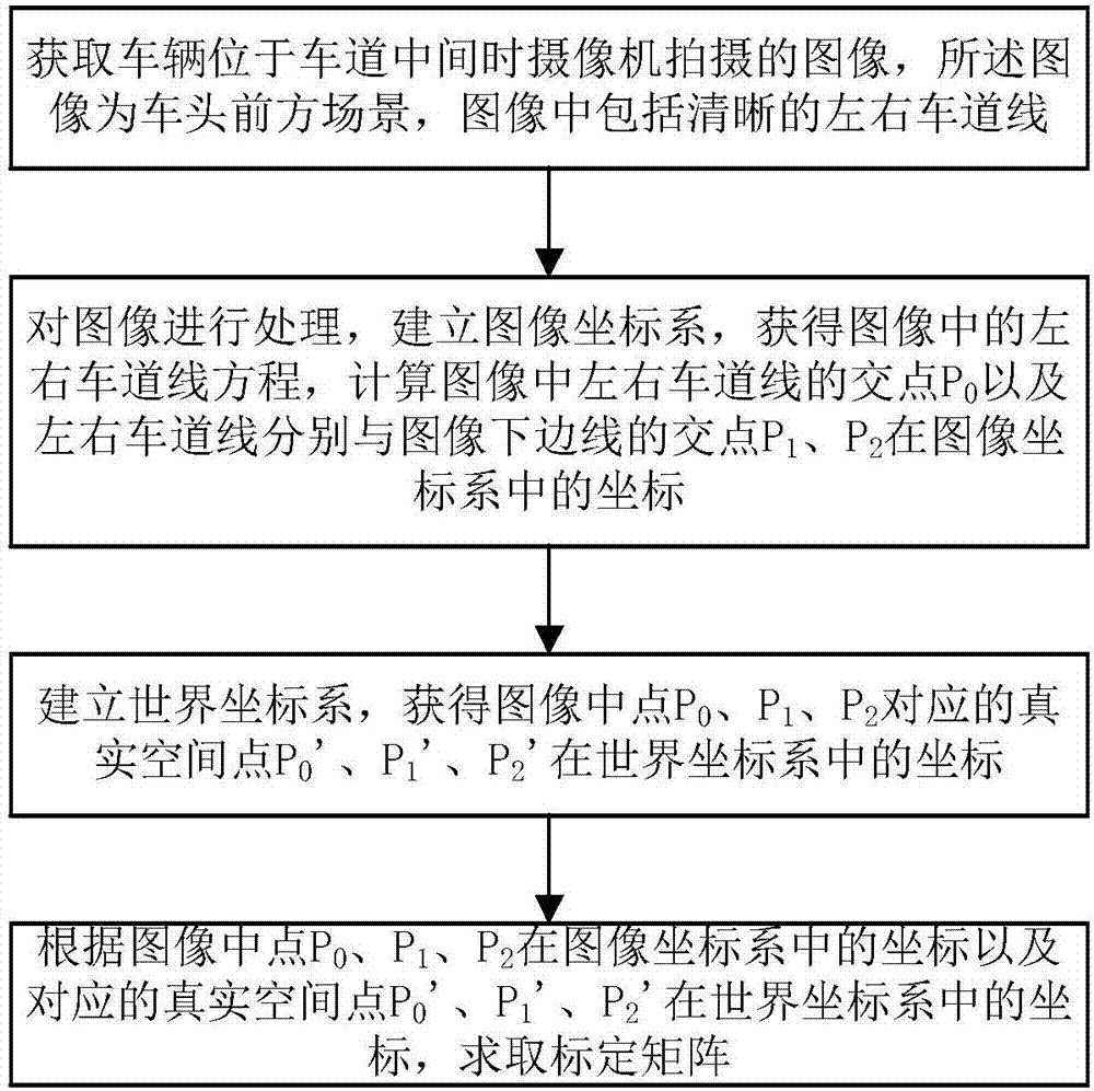
[0018] Such as figure 1 As shown, a kind of vehicle-mounted camera automatic calibration method based on lane line vanishing point provided by the present invention, specifically comprises the following steps:

[0019] Step 1. Obtain the image captured by the camera when the vehicle is in the middle of the lane. The image is the scene in front of the vehicle, and the image includes clear left and right lane lines.

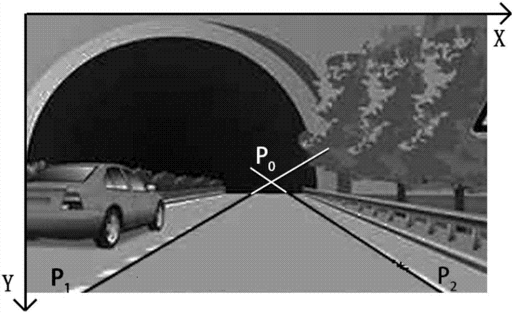
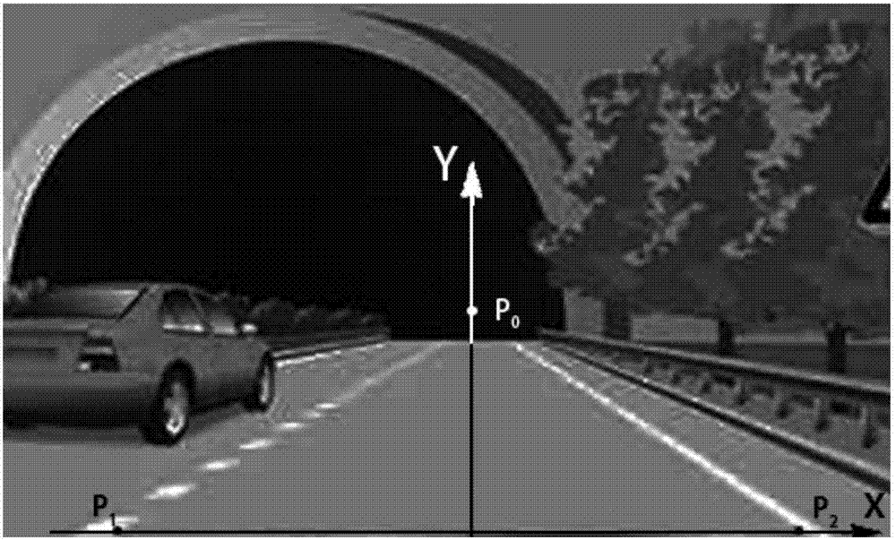
[0020] Step 2. Process the image, establish the image coordinate system, obtain the left and right lane line equations in the image, and calculate the intersection point P of the left and right lane lines in the image 0 And the intersection point P of the left and right lane lines and the lower edge of the image respectively 1 ,P 2 The coordinates in the image coordinate system, specifically include:

[0021] 2.1. Define the first point in the upper left corner of the image as the origin of the coordinates. The horizontal direction of the image is the X axis, an...


PUM


Abstract

The invention provides a vehicle-mounted camera automatic calibration method based on lane line vanishing points. The method comprises the steps that an image photographed by a camera when the vehicle is in the middle of the lane is acquired, wherein the image includes clear left and right lane lines; the image is processed, a left and right lane line equation is acquired, and the coordinates of the intersection point P0 of the left and right lane lines and the intersection points P1 and P2 of the left and right lane lines and the lower side line of the image in an image coordinate system are calculated; a world coordinate system is established, and the coordinates of the real space points P0', P1' and P2' corresponding to the points P0, P1 and P2 in the image in the world coordinate system are acquired; and a calibration matrix is obtained according to the coordinates of the points P0, P1 and P2 in the image in the image coordinate system and the coordinates of the corresponding real space points P0', P1' and P2' in the world coordinate system. According to the method, the vehicle only requires to be driven in the middle of the lane or parked in the middle of the lane and then the photographed image can be automatically processed, and the calibration matrix can be obtained by inquiring the width of the current lane so that the calibration accuracy is high, operation is easy and convenient without artificial intervention and real-time calibration can be performed.

Description

technical field [0001] The invention relates to the field of automobile image processing, in particular to an automatic calibration method for a vehicle-mounted camera based on the vanishing point of a lane line. Background technique [0002] In recent years, advanced driver assistance systems (Advanced Driver Assistance Systems) technology has developed rapidly, and vehicle forward collision warning (Forward Collision Warning) and lane departure warning (Lane Departure Warning) are important parts of it. Both of these functions belong to computer vision applications, which mainly calculate the geometric information of objects in three-dimensional space from the image information obtained by the camera to determine the distance between the vehicle and the obstacle in front and whether the vehicle deviates from the lane line. The premise of realizing the above functions is Accurate calibration of on-board cameras is required. It is generally assumed that there is a simple li...

Claims


Application Information

Patent Timeline
Patent Type & Authority Applications(China)
IPC IPC(8): G06T7/80
CPCG06T7/80
Inventor 薛远陈向成陈高灿李兵张勇程腾
Owner 常州智行科技有限公司
Learn More