Novel multi-purpose magnetic-levitation-type guide rail experiment instrument

A multi-purpose, experimental instrument technology, applied in the field of experimental instruments, can solve the problem of inability to change the inclination of the guide rail at a large angle, and achieve the effect of changing the inclination of the magnetic track at a large angle

Pending Publication Date: 2017-09-05
ZHEJIANG UNIV CITY COLLEGE
View PDF8 Cites 9 Cited by
  • Summary
  • Abstract
  • Description
  • Claims
  • Application Information

AI Technical Summary

Problems solved by technology

[0002] At present, colleges and universities and manufacturers of physical experiment instruments use the traditional air-cushion guide rail mode to suspend sliders for related experiments. The patent No. ZL201620276537.5 authorized on May 30 is a utility model patent for "all-round adjustable simple magnetic levitation mechanical experiment instrument". The above experimental instruments have been continuously improved in the form of slider suspension, and the experimental accuracy and effect have been significantly improved. However, the above-mentioned different types of experimental instruments cannot change the inclination angle of the guide rail at a large angle to improve related experimental results, such as the movement of objects in fluids. It will be very beneficial if we can use a large angle to change the guide rail angle to improve the accuracy and effect of the experiment, such as the research of the research and the measurement of the acceleration of gravity.

Method used


Image

  • Novel multi-purpose magnetic-levitation-type guide rail experiment instrument
  • Novel multi-purpose magnetic-levitation-type guide rail experiment instrument
  • Novel multi-purpose magnetic-levitation-type guide rail experiment instrument

Examples


Embodiment Construction

[0030] The present invention will be further described below in conjunction with the examples. The description of the following examples is provided only to aid the understanding of the present invention. It should be pointed out that for those skilled in the art, without departing from the principle of the present invention, some improvements and modifications can be made to the present invention, and these improvements and modifications also fall within the protection scope of the claims of the present invention.

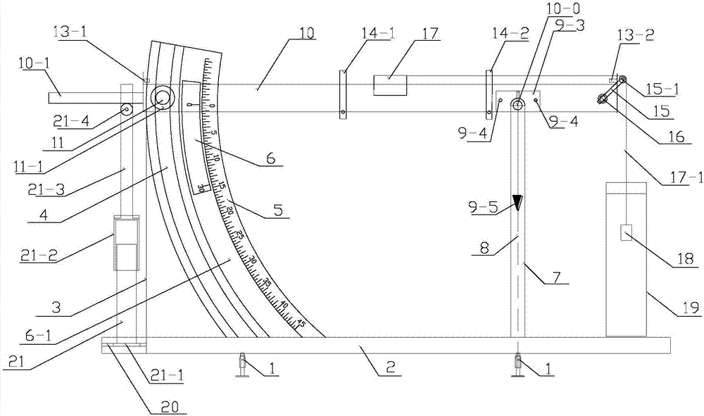
[0031] Such as figure 1 Shown is the front view of the new multi-purpose maglev guideway tester. 1. Leveling support legs, 2. Experimental instrument base, 3. Arc-shaped track frame support rod, 4. Rotating moving shaft chute behind the magnetic track, 5. Main ruler, 6. Micro ruler (vernier ruler), 6-1 , micro-foot chute, 7, magnetic track front rotating shaft support column, 8, magnetic track front rotating shaft support column center line, 9-3, parallel piece,...


PUM


Abstract

The invention relates to a novel multi-purpose magnetic-levitation-type guide rail experiment instrument. The instrument includes levelling support legs, an experiment instrument base, arc rail frame support rods, a rotary moving shaft sliding groove at the rear of a magnetic rail, a main ruler, a micrometer ruler, a micrometer ruler sliding groove, rotation shaft support columns at the front of the magnetic rail, central lines of the rotation shaft support columns at the front of the magnetic rail, a magnetic-rail levelling pointer support frame, the magnetic rail, a rotary moving shaft at the rear of the magnetic rail, a leveling support rod at the tail end of the magnetic rail, a photogate, a pulley frame, pulley frame fixing screws and a sliding block. The lower end of the experiment instrument base is provided with the three levelling support legs, the two sides of the upper portion, corresponding to the two levelling support legs at the front and lower ends of the base respectively, of the base are provided with the rotation shaft support columns at the front of the magnetic rail, and the rotation shaft support columns at the front of the magnetic rail are used for supporting the magnetic rail. The novel multi-purpose magnetic-levitation-type guide rail experiment instrument has the advantages that a measuring cylinder moving groove is specifically formed in the base regarding the project of 'research experiments on movement law of objects in fluid, and the specific placement of a measuring cylinder needs to be determined according to the dip angle of the magnetic rail.

Description

technical field [0001] The patent of the present invention relates to an experimental instrument, in particular to a novel multi-purpose magnetic levitation guide rail experimental instrument. Background technique [0002] At present, colleges and universities and manufacturers of physical experiment instruments use the traditional air-cushion guide rail mode to suspend sliders for related experiments. The patent No. ZL201620276537.5 authorized on May 30 is a utility model patent for "all-round adjustable simple magnetic levitation mechanical experiment instrument". The above experimental instruments have been continuously improved in the form of slider suspension, and the experimental accuracy and effect have been significantly improved. However, the above-mentioned different types of experimental instruments cannot change the inclination angle of the guide rail at a large angle to improve related experimental results, such as the movement of objects in fluids. It will be ...

Claims


Application Information

Patent Timeline
Patent Type & Authority Applications(China)
IPC IPC(8): G09B23/08
CPCG09B23/08
Inventor 张锐波
Owner ZHEJIANG UNIV CITY COLLEGE
Why Eureka
Try Eureka