Electromagnetic forming device and method of fillet of cylindrical part
A technology of electromagnetic forming and fillet forming, which is applied in the field of plastic forming of materials, can solve the problems that the plastic flow of materials around the fillet cannot be realized, and achieve the effects of large wall thickness reduction rate, improved performance and reduced performance
- Summary
- Abstract
- Description
- Claims
- Application Information
AI Technical Summary
Problems solved by technology
Method used
Image
Examples
Embodiment 1
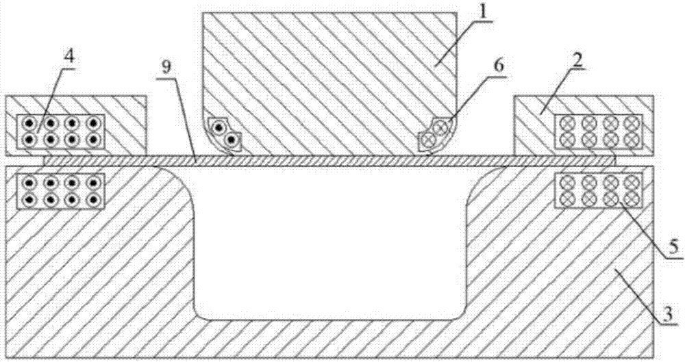
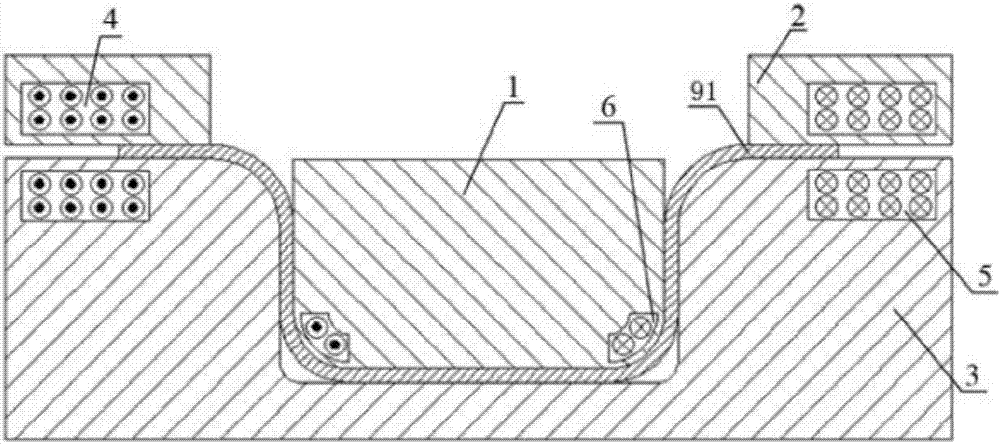
[0053] Such as figure 1 , figure 2 and image 3 As shown, an electromagnetic forming device for rounded corners of cylindrical parts of the present invention, the electromagnetic forming device mainly includes a bulging punch 1, a blank holder 2 and a die 3, and the bulging punch 1 matches the die 3 , the binder ring 2 is movably arranged above the die 3, and is used to press the sheet material 9 to be formed on the die 3. The lower side of the binder ring 2 is embedded with an upper booster coil 4, and the die 3 The lower booster coil 5 is embedded at the position corresponding to the upper booster coil 4 on the upper side of the upper side, and the bulging coil 6 is embedded at the bottom fillet of the bulging punch 1, and the bulging coil 6 is embedded along the The rounded corners of the bottom are arranged in an arc shape, and the electromagnetic forming device also includes at least one power supply module for supplying power to the upper booster coil 4 , the lower bo...
Embodiment 2
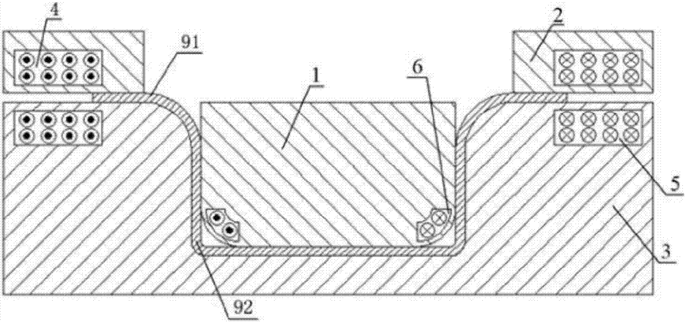
[0058] Such as Figure 4 , Figure 5 and Figure 6 As shown, an electromagnetic forming device for rounded corners of cylindrical parts of the present invention, the electromagnetic forming device mainly includes a bulging punch 1, a blank holder 2 and a die 3, and the bulging punch 1 matches the die 3 , the binder ring 2 is movably arranged above the die 3, and is used to press the sheet material 9 to be formed on the die 3. The lower side of the binder ring 2 is embedded with an upper booster coil 4, and the die 3 The lower booster coil 5 is embedded at the position corresponding to the upper booster coil 4 on the upper side of the upper side, and the bulging coil 6 is embedded at the bottom fillet of the bulging punch 1, and the bulging coil 6 is embedded along the The rounded corners of the bottom are arranged in an arc shape, and the electromagnetic forming device also includes at least one power supply module for supplying power to the upper booster coil 4 , the lower ...
Embodiment 3
[0063] Such as Figure 7 to Figure 11 As shown, an electromagnetic forming device for rounded corners of cylindrical parts of the present invention, the electromagnetic forming device mainly includes a bulging punch 1, a blank holder 2 and a die 3, and the bulging punch 1 matches the die 3 , the binder ring 2 is movably arranged above the die 3, and is used to press the sheet material 9 to be formed on the die 3. The lower side of the binder ring 2 is embedded with an upper booster coil 4, and the die 3 The lower booster coil 5 is embedded at the position corresponding to the upper booster coil 4 on the upper side of the upper side, and the bulging coil 6 is embedded at the bottom fillet of the bulging punch 1, and the bulging coil 6 is embedded along the The rounded corners of the bottom are arranged in an arc shape, and the electromagnetic forming device also includes at least one power supply module for supplying power to the upper booster coil 4 , the lower booster coil 5 ...
PUM
 Abstract
Description
Claims
Application Information
 - R&D Engineer
- R&D Manager
- IP Professional
- Industry Leading Data Capabilities
- Powerful AI technology
- Patent DNA Extraction
Browse by: Latest US Patents, China's latest patents, Technical Efficacy Thesaurus, Application Domain, Technology Topic, Popular Technical Reports.
© 2024 PatSnap. All rights reserved.Legal|Privacy policy|Modern Slavery Act Transparency Statement|Sitemap|About US| Contact US: help@patsnap.com


