Oil gas recovery system

An oil and gas recovery system, oil and gas technology, applied in the recovery of liquid hydrocarbon mixture, vapor condensation, petroleum industry, etc., can solve the problems of reduced adsorption capacity, small processing capacity, inconvenience, etc., to reduce operating costs, reduce regeneration frequency, and increase processing. effect of ability

Inactive Publication Date: 2013-01-30
陈玲海
View PDF2 Cites 31 Cited by
  • Summary
  • Abstract
  • Description
  • Claims
  • Application Information

AI Technical Summary

Problems solved by technology

The defect of this oil and gas recovery technology is that in the case of relatively large oil and gas production, after a short oil and gas adsorption process, the adsorbent will soon enter a saturated state, the adsorption capacity will decrease, and it will soon enter the desorption process. The entire oil and gas recovery process, desorption The process takes a long time, resulting in incomplete oil and gas treatment process, discontinuous production, small processing capacity, and inconvenience to users

Method used


Image

  • Oil gas recovery system
  • Oil gas recovery system

Examples


Embodiment Construction

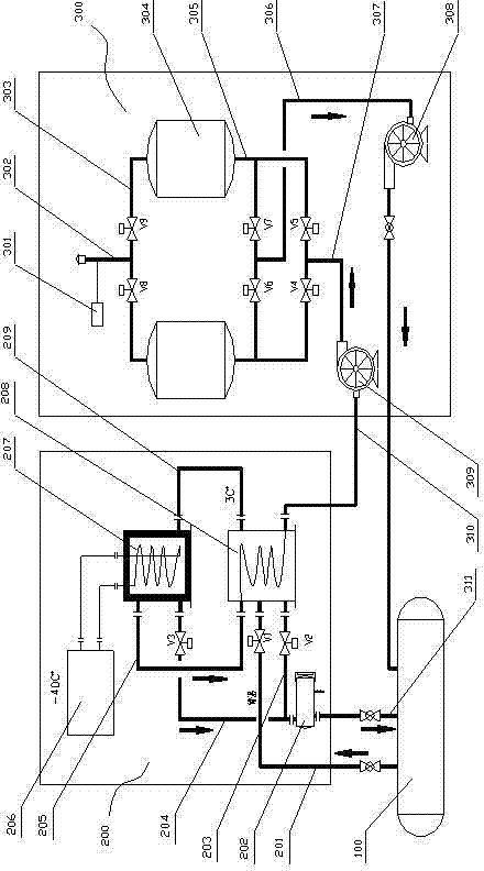
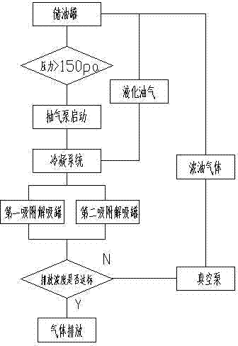
[0010] see figure 1 and figure 2 , the present invention relates to an oil and gas recovery system, which includes an adsorption device 300 and a condensation device 200. The adsorption device is provided with 307, an oil gas exhaust pipe 302 after adsorption and a desorbed oil gas return pipe 306. The condensation device is provided with a waiting Condensed oil and gas inlet pipe 201, condensed oil and gas exhaust pipe 210 and condensate return pipe 211, the condensed oil and gas exhaust pipe of the condensing device is connected to the oil inlet pipe to be adsorbed of the adsorption device. When the source of oil and gas is the oil tank 100 of the gas station and / or the fuel tank of the car, the oil and gas inlet pipe to be condensed can be connected to the oil and gas collection equipment or the discharge port of the oil tank / tank, and the desorbed oil and gas return pipe and the condensate return pipe can be connected to the oil Tank, in order to realize the treatment an...


PUM


Abstract

The invention relates to an oil gas recovery system. The oil gas recovery system comprises an adsorption unit and a condensing unit, wherein a gas inlet pipe for oil gas to be adsorbed, an exhaust pipe for adsorbed oil gas and a return pipe for desorbed oil gas are arranged on the adsorption unit; a gas inlet pipe for oil gas to be condensed, an exhaust pipe for condensed oil gas and a return pipe for condensate are arranged on the condensing unit; the exhaust pipe for the condensed oil gas of the condensing unit is connected with the gas inlet pipe of the oil gas to be adsorbed of the adsorption unit; a first adsorption / desorption tank and a second adsorption / desorption tank are arranged on the adsorption unit to alternately adsorb and desorb the oil gas; and two condensing plants namely an oil gas heat exchanger and a cold box are arranged on the condensing unit to sequentially condense the oil gas. The oil gas recovery system is high in treatment capacity and recovery efficiency, can continuously work, and is mainly suitable for recovering the oil gas generated during oil injection of a buried oil tank of a gas station and refueling of a fuel tank of an automobile.

Description

technical field [0001] The invention relates to an oil gas recovery system, which is mainly suitable for the recovery of oil gas generated during the oil filling process of buried oil tanks in gas stations and automobile oil tanks. Background technique [0002] In all gas stations in cities and villages, during the oil filling process of buried oil tanks, as the oil level rises, a large amount of oil gas is discharged into the air along with the breathing valve of the oil tank; As the surface rises, the oil and gas in the fuel tank are also discharged into the air. The oil and gas discharged into the air is not only a waste of energy, but also pollutes the environment, and because it is a flammable and explosive gas, it also poses a huge safety hazard. Therefore, the recovery of oil and gas is not only effective in saving Energy, reducing air pollution, and greatly reducing the safety hazards of gas stations, making the operation process of refueling safer. [0003] The oi...

Claims


Application Information

Patent Timeline
Patent Type & Authority Applications(China)
IPC IPC(8): C10G5/00C10G5/02C10G5/06B01D5/00B01D53/04B01D53/00B67D7/06
Inventor 陈玲海
Owner 陈玲海
Why Eureka
Try Eureka