
Overturning propeller device

A propeller and reversible technology, which is applied in the field of reversible propeller devices, can solve the problems of large vehicle body width, inability to drive on the road, and complicated ground driving devices, and achieve the goals of reducing the weight of the vehicle, improving flight efficiency, and reducing the width of the vehicle body Effect

Pending Publication Date: 2017-09-08
张福创
View PDF2 Cites 3 Cited by
  • Summary
  • Abstract
  • Description
  • Claims
  • Application Information

AI Technical Summary

Problems solved by technology

Its shortcoming is that it is impossible to share a set of driving devices in the land travel state and the flight state
In addition, in order to facilitate road driving, it is necessary to use segmented propellers, and arrange the left and right blades at designated positions, resulting in inconvenient folding
[0003] CN104309403A patent application discloses a new type of circular rail hollow wheel and flying car system. A propeller parallel to the ground is installed in the hollow wheel. Although the propeller does not need to be retracted and retracted, when the size of the propeller meets the manned flight, the car body will definitely be damaged. The width is too large to drive on the road, and the ground driving device is complex and unreliable
[0004] Both of the above patent applications rely entirely on multi-axis flight, which is inefficient compared to fixed-wing aircraft flight

Method used


Image

  • Overturning propeller device
  • Overturning propeller device
  • Overturning propeller device

Examples


Embodiment 1

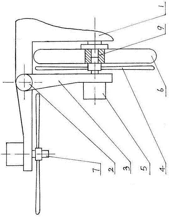
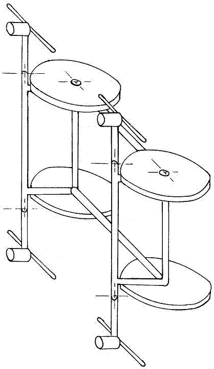
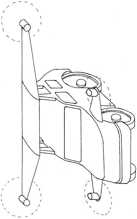
[0022] Example 1 (see figure 1 , figure 2 , image 3 ).

[0023] 1. The car body 1 is rotationally connected with one end of the propeller bracket 3 through the rotating shaft 2, so that the propeller bracket 3 can rotate up and down. The other end of the propeller bracket 3 is equipped with a propeller 4, and a transmission shaft 7 is arranged on the axis of the propeller 4. The propeller 4 is connected to the driving device 5. The driving device 5 is installed on the propeller bracket 3 and is used to drive the propeller 4 to rotate.

[0024] 2. When the propeller bracket 3 rotates upwards to the flying position, the axis of the propeller 4 is arranged vertically. At this time, the thrust generated by the high-speed rotation of the propeller 4 makes the car body 1 take off and fly. When landing, as the speed of the propeller 4 gradually decreases, after the height of the car body 1 gradually decreases and returns to the ground, the propeller bracket 3 also starts to rota...

Embodiment 2

[0028] Example 2 (see Figure 4 , Figure 5 , figure 2 , image 3 ).

[0029] 1. The structural difference between this embodiment and Embodiment 1 is that: on the one hand, the transmission shaft 7 is arranged on the propeller bracket 3 and connected with the driving device 5, and its axis no longer coincides with the axis of the propeller 4; in addition, the propeller bracket 3 is also provided with The propeller clutch device 8 is used for disconnecting the connection between the drive device 5 and the propeller 4 in the state of land travel. On the other hand, the retracting and retracting of the propeller support 3 in this embodiment is accomplished by the retracting device.

[0030] 2. After the vehicle body 1 lands on the ground and the propeller 4 stops rotating, the control system not only controls the retractable device so that the propeller support 3 can be smoothly retracted to the land position, but also activates the wheel clutch device 9 . While the drive ...


PUM


Abstract

An overturning propeller device applied to a multi-shaft air-land dual-purpose vehicle comprises a vehicle body and is characterized in that the vehicle body is in rotary connection with one end of a propeller support through a rotary shaft to make the propeller support vertically rotatable, a propeller is installed at the other end of the propeller support and is connected with a driving device, and the driving device installed on the propeller support or the vehicle body and used for driving the propeller to rotate. When the propeller support upwards rotates to a flying position, the axis of the propeller is vertically arranged. When the propeller support is downwards turned from the flying position to a land running position, the propeller is arranged to be close to wheels, and accordingly the width of the vehicle body is effectively decreased. The overturning propeller device is suitable for running on highways and can also use one driving device in land running and flying to lighten the weight. If the propeller support is designed into wings, and the flying efficiency can be also improved.

Description

technical field [0001] The invention relates to the technical field of multi-axis air-and-land vehicles, in particular to a flip-type propeller device. Background technique [0002] CN102275476 A patent application discloses a vertical take-off and landing flying vehicle. In the state of land travel, the retractable mechanism retracts the propeller on both sides of the front and rear of the vehicle along the horizontal direction. Open horizontally. Its shortcoming is: can't realize that the land line state and the flight state share a set of driving devices. In addition, in order to facilitate road driving, it is necessary to use segmented propellers, and arrange the left and right blades at designated positions, resulting in inconvenient folding. [0003] CN104309403A patent application discloses a new type of circular rail hollow wheel and flying car system. A propeller parallel to the ground is installed in the hollow wheel. Although the propeller does not need to be re...

Claims


Application Information

Patent Timeline
IPC IPC(8): B60F5/02
CPCB60F5/02
Inventor 张福创
Owner 张福创
Learn More