Low-power-action high-speed magnetic levitation vehicle suspension frame device

A low power, suspension frame technology, applied in the direction of electric vehicles, vehicle parts, electric traction, etc., can solve the problems of potential safety hazards, unfavorable suspension control, high manufacturing costs, etc., to facilitate installation and disassembly, facilitate suspension control, and improve suspension The effect of stability

Active Publication Date: 2017-09-08
SOUTHWEST JIAOTONG UNIV
View PDF15 Cites 7 Cited by
  • Summary
  • Abstract
  • Description
  • Claims
  • Application Information

AI Technical Summary

Problems solved by technology

[0004] There are certain deficiencies in the existing suspension frame technical solutions, which are mainly manifested in the following points: First, the suspension frames on both sides are connected by rigid beam frames, that is, the movements of the left and right suspension modules are coupled together, which will cause the left and right modules of the suspension frame to In addition, the suspension frame coupled with the left and right suspension modules is more sensitive to the line conditions, which intensifies the dynamic effect between the vehicle and the track; the second is that the setting of two sets of beam frames makes the structure of the entire suspension frame complex. The manufacturing cost is high and maintenance is difficult, and it is not conducive to the weight reduction of the suspension frame; the third is that the secondary suspension system is set at the four corners of the suspension frame, which is not conducive to suspension control; the fourth is that the front and rear "semi-suspension frames" are connected by a central longitudinal beam , the longitudinal beam will bear a large longitudinal force in actual operation, so it is easy to cause fatigue cracks and cause safety hazards

Method used


Image

  • Low-power-action high-speed magnetic levitation vehicle suspension frame device
  • Low-power-action high-speed magnetic levitation vehicle suspension frame device
  • Low-power-action high-speed magnetic levitation vehicle suspension frame device

Examples


Embodiment Construction

[0023] The present invention will be further described below in conjunction with accompanying drawing and specific embodiment:

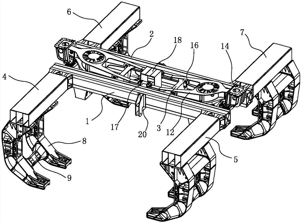
[0024] Such as figure 1 As shown, a kind of low dynamic effect high-speed maglev vehicle suspension frame device provided by the present invention includes a beam frame unit equipped with a secondary suspension system, and longitudinal beams are respectively installed on both sides of the two ends of the beam frame unit, and the ends of the longitudinal beams are A suspension frame unit is installed.

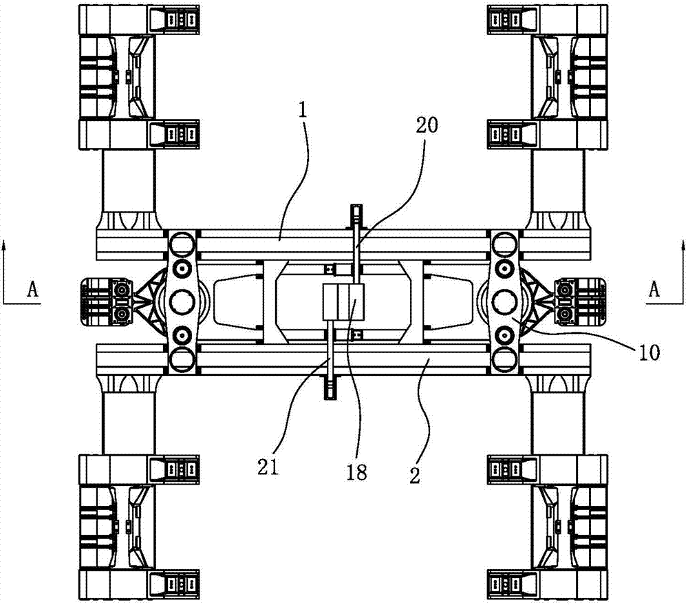
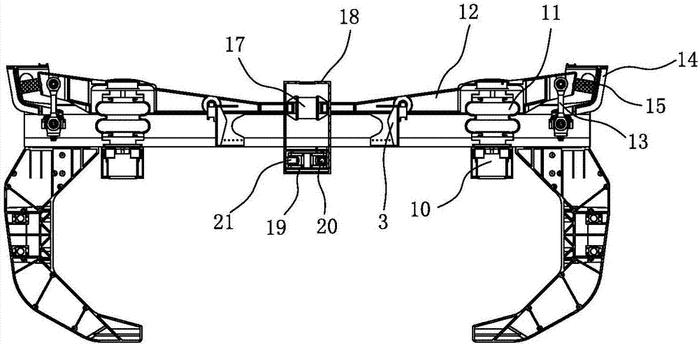
[0025] The beam frame unit includes a first beam 1, a second beam 2, a beam connector 3, an air spring mount 10 and a Z-shaped traction unit. The first beam 1 and the second beam 2 are arranged in parallel, and the beam connectors 3 are evenly distributed on the second beam. The first beam 1 and the second beam 2 are used for connecting the first beam 1 and the second beam 2 . The beam connectors 3 are located at both ends of the first beam 1 and the...


PUM


Abstract

The invention discloses a low-power-action high-speed magnetic levitation vehicle suspension frame device. The device comprises a middle cross beam frame unit with a secondary suspension system, and the two sides of the two ends of the cross beam frame unit are both provided with a longitudinal beam; suspension frame units are mounted at the ends of the longitudinal beams. The suspension frame device omits a half-suspension-frame design mode of an existing magnetic levitation vehicle suspension frame, that is, the structure in which a middle longitudinal beam is used for connecting a front half suspension frame with a rear half suspension frame is not used, instead, only one middle cross beam frame unit is used; the suspension frame units are fixed on the two sides of the beam frame unit by means of the four longitudinal beams. By means of the unique suspension frame structure design, certain movement decoupling can be achieved, and the adaptability of a suspension frame to a line is enhanced; in addition, the power effect between the suspension frame device and the line can be effectively reduced by means of the middle secondary suspension, vehicle rail coupling vibration is inhibited, and the suspension stability is improved.

Description

technical field [0001] The invention belongs to the technical field of high-speed maglev vehicles, and in particular relates to a suspension frame device for low-power high-speed maglev vehicles. Background technique [0002] The importance of the suspension frame as the main component of the high-speed maglev vehicle running mechanism is self-evident. The suspension frame of the existing high-speed maglev vehicle is composed of two "semi-suspension frames" connected by a central longitudinal beam. The beam connects the front and rear semi-suspension frames to form a complete suspension frame. [0003] In the existing suspension frame technical scheme, the secondary suspension system is arranged on the upper part of the suspension frame at the four corners of the suspension frame, and each suspension frame contains four sets of secondary suspension systems. The secondary suspension system is responsible for transmitting the suspension force, partial traction force, braking...

Claims


Application Information

Patent Timeline
Patent Type & Authority Applications(China)
IPC IPC(8): B60L13/04
CPCB60L13/04Y02T30/00
Inventor 马卫华胡俊雄罗世辉
Owner SOUTHWEST JIAOTONG UNIV
Why Eureka
Try Eureka