Detachable cutter wheel rack

A technology of cutter wheel frame and hole cutter, which is applied in the field of processing tools, can solve the problems that the cutter wheel without holes can not be installed on the cutter head, and achieve the effect of saving the assembly process, avoiding the problem of installation accuracy, and saving installation time

Pending Publication Date: 2017-09-08
JIAXING WORLDIA DIAMOND TOOLS CO LTD
View PDF10 Cites 0 Cited by
  • Summary
  • Abstract
  • Description
  • Claims
  • Application Information

AI Technical Summary

Problems solved by technology

For example, unlike the traditional cutter wheel and the cutter shaft, there is no shaft hole connecting the two disks on the non-perforated cutter wheel, and the traditional cutter shaft will not be able to install the non-perforated cutter wheel on the cutter head

Method used


Image

  • Detachable cutter wheel rack
  • Detachable cutter wheel rack
  • Detachable cutter wheel rack

Examples


Embodiment Construction

[0038] The technical solutions in the embodiments of the present invention will be clearly and completely described below in conjunction with the drawings in the embodiments of the present invention. Apparently, the described embodiments are only some of the embodiments of the present invention, but not all of them. Based on the embodiments of the present invention, all other embodiments obtained by persons of ordinary skill in the art without making creative efforts belong to the protection scope of the present invention.

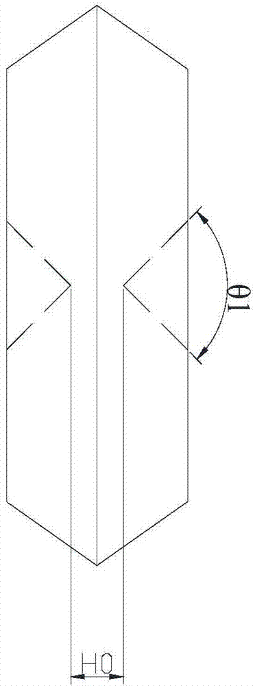
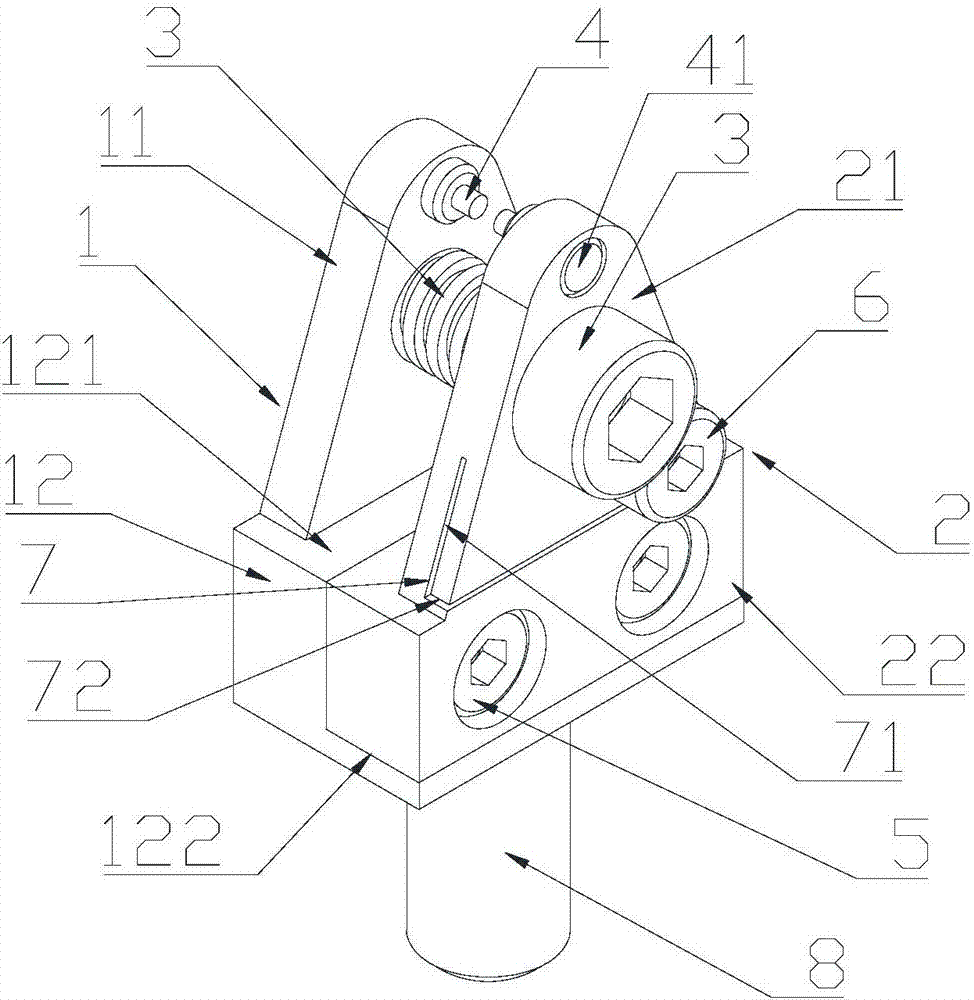
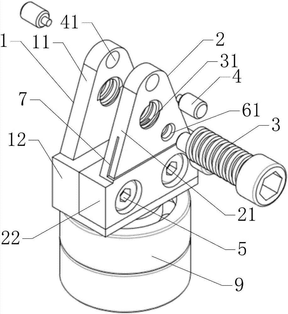
[0039] An embodiment of the present invention provides a detachable cutter wheel frame, which is applied to a non-perforated cutter wheel. For a structural schematic diagram of the non-perforated cutter wheel, refer to figure 1 , the center of the disc surface of the non-porous cutter wheel is provided with a non-connected positioning groove. see figure 2 to Figure 5 , is a specific embodiment of the cutter wheel frame of the present invention. The ...


PUM


Abstract

The invention discloses a detachable cutter wheel rack. The cutter wheel rack is applied to imperforate cutter wheels. The cutter wheel rack comprises a first substrate and a second substrate, the second substrate is detachably installed on the first substrate, and the first substrate comprises a first supporting arm and a stepped first supporting base; the second substrate comprises a second supporting base and a second supporting arm which are oppositely arranged, inner walls of the first supporting arm and the second supporting arm are separately and coaxially provided with a locating shaft, a cross section of the locating shaft is in circular shape, and a locating slot of an imperforate cutter wheel is clamped on the locating shaft; the first supporting arm and the second supporting arm are respectively and coaxially opened with first through holes, the cutter wheel rack also comprises a fastener, and the fastener passes through the first through holes in order and is fastened to the first supporting arm and the second supporting arm. The cutter wheel rack has a simple structure, and can be matched with the imperforate cutter wheel for usage.

Description

technical field [0001] The invention relates to the field of processing tools, in particular to a detachable cutter wheel frame. Background technique [0002] The traditional diamond cutter wheel is integrated with the cutter shaft, and the cutter wheel is provided with a shaft hole connecting the two disk surfaces. When in use, the cutter shaft passes through the shaft hole and cooperates with the cutter wheel. During use, the contact area between the inner hole of the cutter wheel and the cutter shaft is large, the resistance to the rotation of the cutter wheel is large, and the rotation of the cutter wheel is not smooth enough. At the same time, the long-term continuous friction between the cutter wheel and the cutter shaft causes the gap between the cutter wheel and the cutter shaft The gap between them becomes larger, making it easier for dust and waste to enter the gap, resulting in chip jamming, slipping, and poor rotation. [0003] With the diversification of cuttin...

Claims


Application Information

Patent Timeline
IPC IPC(8): C03B33/00C03B33/10
CPCC03B33/00C03B33/105
Inventor 唐文林
Owner JIAXING WORLDIA DIAMOND TOOLS CO LTD
Why Eureka
Try Eureka