

Electricity-leakage-preventive piezoelectric ceramic igniter body plastic shell
A technology of piezoelectric ceramics and igniters, which is applied in the field of leakage-proof voltage electric ceramic igniter body plastic shells, can solve problems such as failure to achieve results, leakage, and complicated procedures, and achieve the effect of simplifying the assembly process and eliminating hidden dangers of leakage
Inactive Publication Date: 2015-04-29
阴运和
View PDF4 Cites 0 Cited by
- Summary
- Abstract
- Description
- Claims
- Application Information
AI Technical Summary
Problems solved by technology
In the assembly process, the iron cap must be screwed tightly with the plastic shell. Such a structure is extremely complicated in the process of mechanized assembly.
In order to simplify the assembly process, the iron cap was deformed several times, but the desired effect was not achieved
And the distance between the iron cap and the wire groove is too close, it is easy to cause leakage
Method used
View moreImage
Smart ImageViewing Examples

Examples
Embodiment Construction
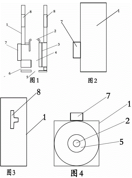
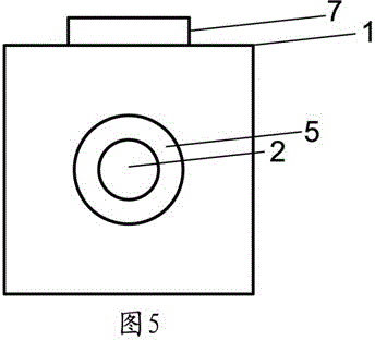
[0013] exist figure 1 , 2 , 3, 4, and 5, when the present invention is matched and assembled, in the plastic shell 1 of the body, a small cap nail is pressed into the small cap nail hole 2, and a conductive nail is pressed into the piezoelectric ceramic from the bottom hole 5 at position 3. At position 4, put the copper sheet at position 4, and put piezoelectric ceramics at position 4 from the bottom hole 5. Press the metal plate into the electrode square hole 6, so that the plastic shell of the main body and the parts to be assembled are integrated.
Login to View More PUM
 Abstract
The invention discloses an electricity-leakage-preventive piezoelectric ceramic igniter body plastic shell (hereinafter referred to a body). The body is characterized in that the whole body is formed by pressure injection of engineering plastic; a rectangular hole is formed below a wire guide groove of the body; after piezoelectric ceramic is assembled, a square or round metal plate is pressed into the hole to close and fix the piezoelectric ceramic and serve as a cathode of the piezoelectric ceramic.
Description
technical field [0001] The invention relates to a body plastic shell of a leakage-proof voltage electric ceramic igniter, which is especially suitable for a piezoelectric ceramic igniter for a lighter. Background technique [0002] At present, in the known piezoelectric ceramic igniter body plastic shell, the lower part of the wire groove is a cylindrical shape with external threads. Cooperate with the iron cap with internal thread to block the piezoelectric ceramic and serve as the negative electrode of the whole piezoelectric ceramic igniter. In the assembly process, the iron cap must be screwed tightly with the plastic shell, and the process of mechanized assembly of such a structure is extremely complicated. In order to simplify the assembly process, the iron cap was deformed several times, but the desired effect was not achieved. And if the distance between the iron cap and the wire groove is too close, it is easy to cause electric leakage. Contents of the invention...
Claims
Login to View More Application Information
Patent Timeline
 IPC IPC(8): F23Q3/00
Inventor阴运和
Owner阴运和