
Positioning fixture for medium and low speed maglev track J III telescopic joint installation

A magnetic levitation track and positioning tooling technology, which is applied to track, track laying, track maintenance, etc., can solve the problems of speeding up the installation progress of JⅢ expansion joints, good use effect, and inability to position the mounting seat, so as to solve the problem of inability to position and use the effect Good, high positioning accuracy effect

Active Publication Date: 2017-09-08
CHINA RAILWAY FIRST GRP CO LTD +1
View PDF8 Cites 1 Cited by
  • Summary
  • Abstract
  • Description
  • Claims
  • Application Information

AI Technical Summary

Problems solved by technology

[0003] The technical problem to be solved by the present invention is to provide a positioning tool for the installation of the JⅢ type telescopic joint of the medium and low speed maglev track in view of the deficiencies in the above-mentioned prior art, Its simple structure and reasonable design can solve the problem that the JⅢ type expansion joint mounting seat cannot be positioned. By ensuring the positioning accuracy of the four JⅢ type expansion joint mounting bases, the positioning installation of the JⅢ type expansion joint is realized, with high positioning accuracy and small error , to speed up the installation progress of the JⅢ type expansion joint, and the use effect is good

Method used


Image

  • Positioning fixture for medium and low speed maglev track J III telescopic joint installation
  • Positioning fixture for medium and low speed maglev track J III telescopic joint installation
  • Positioning fixture for medium and low speed maglev track J III telescopic joint installation

Examples


Embodiment Construction

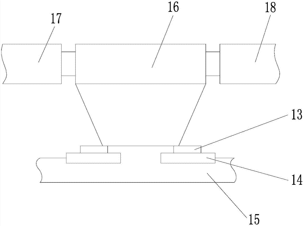
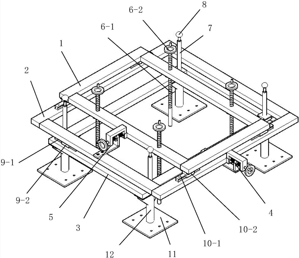
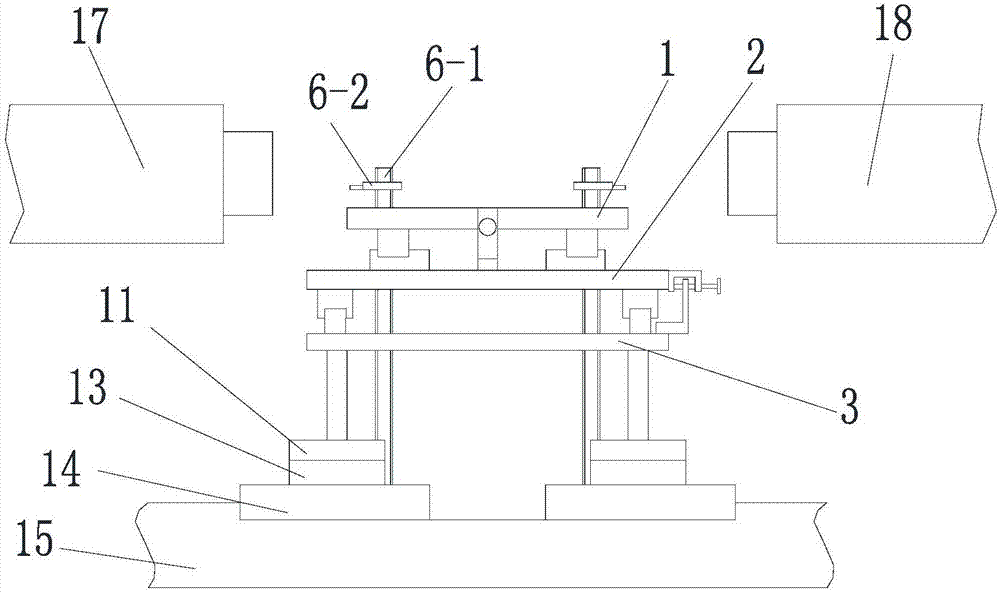
[0035] like figure 2 As shown, the present invention includes a main frame body 3, and a longitudinal adjustment mechanism, a horizontal adjustment mechanism and a height adjustment mechanism for adjusting the installation position of the JIII type telescopic joint mounting seat. The main frame body 3 is provided with a The prism 8 matched with the instrument; the lateral adjustment mechanism includes a lateral adjustment frame body 2 and a first screw moving mechanism 4 for driving the lateral adjustment frame body 2 to move laterally, and the lateral adjustment frame body 2 and the main frame body 3 are slidably matched , the first screw moving mechanism 4 is installed between the horizontal adjustment frame body 2 and the main frame body 3; the longitudinal adjustment mechanism includes a longitudinal adjustment frame body 1 and a second screw rod for driving the longitudinal adjustment frame body 1 to move longitudinally The moving mechanism 5, the longitudinal adjustment...


PUM


Abstract

The invention discloses a positioning fixture for medium and low speed maglev track J III telescopic joint installation. The fixture comprises a main frame, a longitudinal adjustment mechanism, a transverse adjustment mechanism and a height adjustment mechanism, wherein the longitudinal adjustment mechanism, the transverse adjustment mechanism and the height adjustment mechanism are used for installation position adjustment of J III telescopic joint installation bases. Prisms matched with a total station are arranged on the main frame; the transverse adjustment mechanism comprises a transverse adjustment frame and a first lead screw moving mechanism used for driving the transverse adjustment frame to move transversely; the longitudinal adjustment mechanism comprises a longitudinal adjustment frame and a second lead screw moving mechanism used for driving the longitudinal adjustment frame to move longitudinally; positioning steel plates used for positioning the installation position of the J III telescopic joint installation bases are arranged below the main frame. By means of the positioning fixture, the problem that the J III telescopic joint installation bases cannot be positioned can be solved, and the positioning accuracy of the four J III telescopic joint installation bases is guaranteed, so that positioning installation of a J III telescopic joint is achieved, the positioning accuracy is high, the error is small, and the installation progress of the J III telescopic joint is accelerated.

Description

technical field [0001] The invention belongs to the technical field of medium and low speed maglev track erection equipment, and relates to a positioning tool, in particular to a positioning tool for installing a JIII-type expansion joint of a medium and low speed maglev track. Background technique [0002] The medium and low-speed maglev track is composed of maglev rail rows assembled, and the maglev rail row is connected with the maglev rail row through expansion joints. According to the expansion and contraction of different needs, five types of expansion joints are designed, namely JⅠ type and JⅡ type. , JⅢ, JⅢG and JⅣ. The length of the JⅢ expansion joint is 1.2 meters and the weight is 1.6 tons, and the installation accuracy of the JⅢ expansion joint is very high. If the JⅢ expansion joint is directly hoisted The joint is connected with the magnetic levitation rail row. Due to the large volume and heavy weight of the JⅢ type expansion joint, it is easy to cause damage ...

Claims


Application Information

Patent Timeline
Patent Type & Authority Applications(China)
IPC IPC(8): E01B25/30E01B25/32E01B29/00
CPCE01B25/30E01B25/32E01B29/00
Inventor 王文飞李育朝时红军杜昆朱勇坚曹德志颜景润张默志
Owner CHINA RAILWAY FIRST GRP CO LTD
Learn More