
Reinforcing steel tube grouting anchor construction method applicable to retaining wall protection slope

A technology of grouting anchor rods and construction methods, which is applied to sheet pile walls, foundation structure engineering, construction, etc., and can solve the problems of long working cycle, poor adaptability of reinforced anchor rod retaining walls, cumbersome procedures of anchor cable retaining walls, etc. problem, to achieve the effect of shortening the construction period

Inactive Publication Date: 2017-09-08
CHINA METALLURGICAL CONSTR ENG GRP
View PDF4 Cites 0 Cited by
  • Summary
  • Abstract
  • Description
  • Claims
  • Application Information

AI Technical Summary

Problems solved by technology

[0002] The traditional slope protection construction of retaining wall usually adopts steel anchor rod or anchor cable type to protect the slope of the retaining wall. It is not conducive to the rapid formation of retaining wall slope protection under complex geological conditions, and the quality of retaining wall slope protection is difficult to guarantee
Secondly, under complex geological conditions, the hole formation of retaining wall slope protection has a higher probability of collapse, which is not conducive to the formation and construction of retaining wall slope protection, and it is difficult to meet the requirements of project quality and construction period; this is mainly due to the hole formation of retaining wall slope protection. and the construction technology of the bolt form need to be improved

Method used


Image

  • Reinforcing steel tube grouting anchor construction method applicable to retaining wall protection slope
  • Reinforcing steel tube grouting anchor construction method applicable to retaining wall protection slope
  • Reinforcing steel tube grouting anchor construction method applicable to retaining wall protection slope

Examples


Embodiment Construction

[0017] The present invention will be further described below in conjunction with the accompanying drawings and specific embodiments.

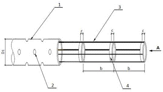
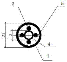
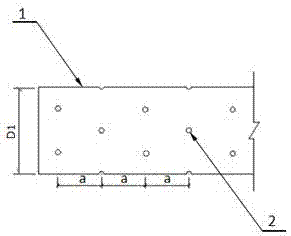
[0018] Such as figure 1 , 2 , Shown in 3 and 4, the reinforced steel pipe grouting anchor bolt construction method suitable for retaining wall slope protection once of the present invention shortens the construction period of retaining wall slope protection, and ensures that the one-time rapid construction of retaining wall slope protection under complex geological conditions form, including the following steps:

[0019] (1) According to the process design requirements, select the steel pipe segment, and open a number of slurry holes on the circumference of the steel pipe segment, and the slurry hole is connected with the inner cavity of the steel pipe segment;

[0020] (2) According to the process design requirements, make a composite steel skeleton; the composite steel skeleton includes a number of lining steel rings and reinforcing steel b...


PUM


Abstract

The invention discloses a reinforcing steel tube grouting anchor construction method applicable to a retaining wall protection slope. A plurality of grout outlet holes are formed in the circumference of a steel tube segment, a combined reinforcement framework composed of a plurality of lining steel rings and reinforcing rebars is manufactured, the lining steel rings are arranged front and back in the length direction of the reinforcing rebars, and the reinforcing rebars are connected with the portions, making contact with the reinforcing rebars, of the outer circumferential faces of the lining steel rings; a plurality of cushion blocks are arranged on the outer side faces of the reinforcing rebars; when the pore-forming depth meets the design requirement, the steel tube segment is pushed in, the combined reinforcement framework is pushed into the steel tube segment, the position is adjusted, a reinforcing steel tube grouting anchor structure is formed, and a reinforcing steel tube grouting anchor is formed after being filled with grout through one-step continuous grouting. According to the manufacturing method, the construction period of the retaining wall protection slope can be shortened, one-step rapid forming of the retaining wall protection slope under the complex geological conditions is ensured, and the special bearing design demands after forming of the retaining wall protection slope under the complex geological conditions can be advantageously met.

Description

technical field [0001] The invention relates to a steel pipe grouting bolt construction method suitable for retaining wall slope protection, in particular to a reinforced steel pipe grouting bolt construction method suitable for retaining wall slope protection. Background technique [0002] The traditional slope protection construction of retaining wall usually adopts steel anchor rod or anchor cable type to protect the slope of the retaining wall. It is not conducive to the rapid formation of retaining wall slope protection under complex geological conditions, and the quality of retaining wall slope protection is difficult to guarantee. Secondly, under complex geological conditions, the hole formation of retaining wall slope protection has a higher probability of collapse, which is not conducive to the formation and construction of retaining wall slope protection, and it is difficult to meet the requirements of project quality and construction period; this is mainly due to ...

Claims


Application Information

Patent Timeline
IPC IPC(8): E02D5/76
CPCE02D5/76
Inventor 陈国民王丰肖荣锋王强
Owner CHINA METALLURGICAL CONSTR ENG GRP
Learn More