Aircraft mounted display module

A technology of airplanes and projectors, applied in the field of airplanes, can solve problems such as inability to see images, time-consuming, and danger

Pending Publication Date: 2017-09-12
GOODRICH LIGHTING SYST
View PDF6 Cites 1 Cited by
  • Summary
  • Abstract
  • Description
  • Claims
  • Application Information

AI Technical Summary

Problems solved by technology

However, such rendered images are fixed in nature and can be costly, time-consuming and dangerous to impose and replace
Also, usually such images cannot be seen at night

Method used


Image

  • Aircraft mounted display module
  • Aircraft mounted display module
  • Aircraft mounted display module

Examples


Embodiment Construction

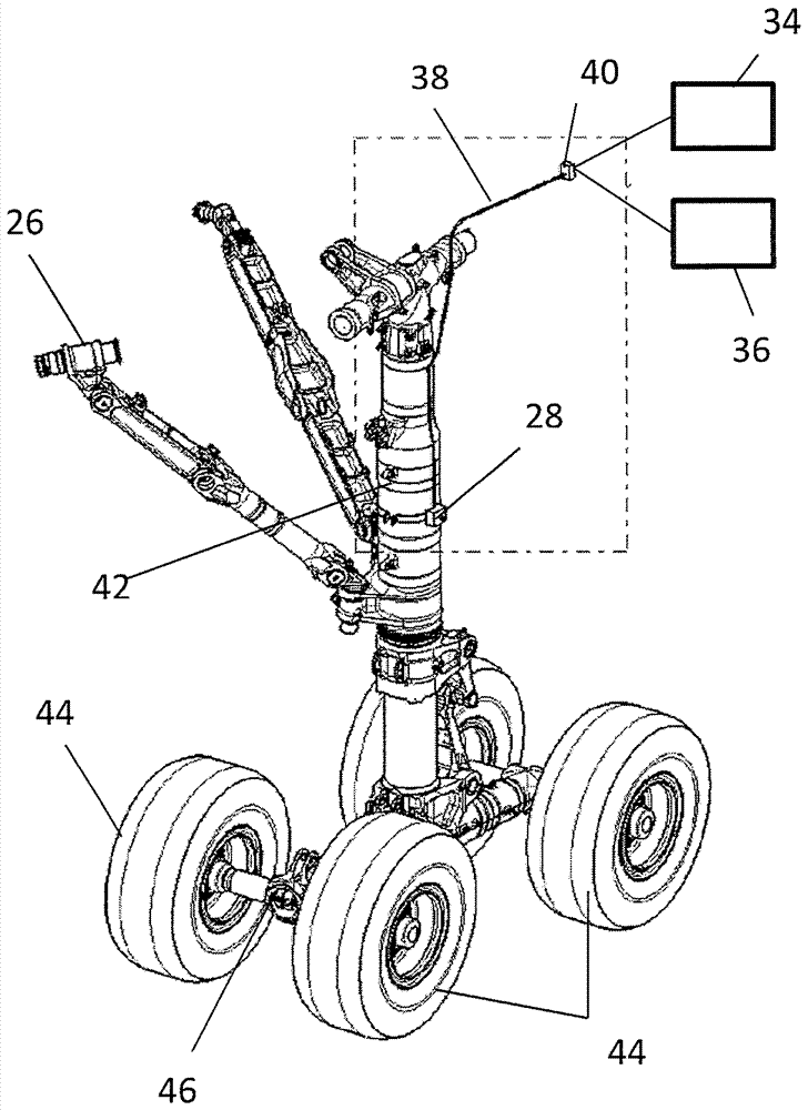
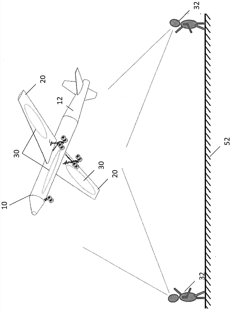
[0029] figure 1 A schematic diagram of an aircraft 10 is shown in . Aircraft 10 includes a fuselage 12 extending from a nose 16 to a tail 18 of the aircraft 10 along a central axis 14 of the aircraft 10 . Wings 20 extend laterally from fuselage 12 to provide lift to aircraft 10 . In some embodiments, the aircraft 10 may also include a horizontal stabilizer 22 extending from the fuselage 12 to the rear of the wing 20 . Aircraft 10 may also include a landing gear assembly that may be deployed for ground operations of aircraft 10 , such as landing and takeoff of aircraft 10 . In some embodiments, the landing gear assembly may include a nose gear assembly 24 and one or more main landing gear assemblies 26, which may be positioned at the wing 20 (eg figure 1 shown), or alternatively, at the fuselage 12. Although figure 1 The illustrated embodiment includes one nose gear assembly 24 and two main gear assemblies 26, although it should be understood that in some embodiments other...


PUM


Abstract

An aircraft includes an aircraft body including one or more exterior surfaces and a projector secured to a component of the aircraft. The projector is configured to selectably project one or more images on the one or more exterior surfaces. A method of displaying a projected image on an aircraft surface includes moving a landing gear assembly of the aircraft from a retracted position to an extending position, activating a projector disposed at the landing gear assembly, and displaying a projected image at the aircraft surface via activation of the projector.

Description

technical field [0001] The subject matter disclosed herein relates to aircraft. More specifically, the present disclosure relates to displays of information that are projected onto aircraft surfaces. Background technique [0002] Recently, it has become increasingly common to see advertisements and other informational messages on items related to commercial air travel. Today, advertisements and other messages are often found on boarding passes, security tags, luggage tags, in-flight entertainment systems, and the like. Some aircraft operators have gone so far as to paint commercial images or advertisements onto various parts of the aircraft structure, such as the wings, vertical tail, or underside of the fuselage. This utilizes normally unused space to increase aircraft operator revenue. However, such rendered images are fixed in nature and can be costly, time-consuming and dangerous to impose and replace. Also, usually such images cannot be seen at night. The art would...

Claims


Application Information

Patent Timeline
IPC IPC(8): B64D47/00G09F21/08
CPCB64C25/10B64D47/02G09F21/10H04N9/3141B64D47/00G09F21/08B64C25/00B60Q3/46G03B29/00G09F19/18
Inventor N.R.瓦尔克A.帕特尔
Owner GOODRICH LIGHTING SYST
Why Eureka
Try Eureka