

Spiral pipeline inner wall walking device
A walking device and screw-type technology, applied in the direction of pipe elements, special pipes, pipes/pipe joints/pipes, etc., can solve the problems of unstable movement of the robot, large radial space, and high spring occupation, and achieve strong driving force, The effect of smooth movement and not easy to twist
- Summary
- Abstract
- Description
- Claims
- Application Information
AI Technical Summary
Problems solved by technology
Method used
Image

Examples
Embodiment 1
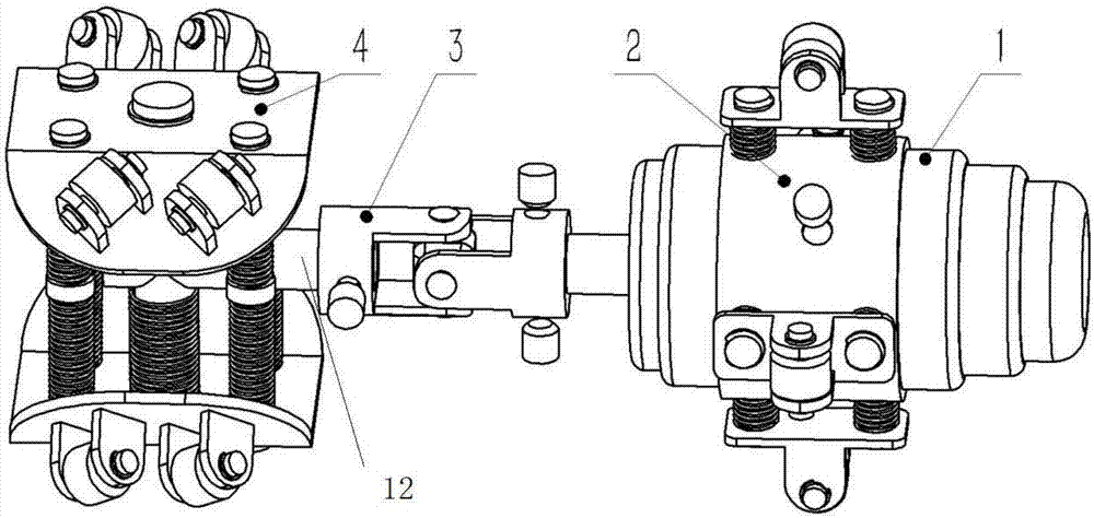
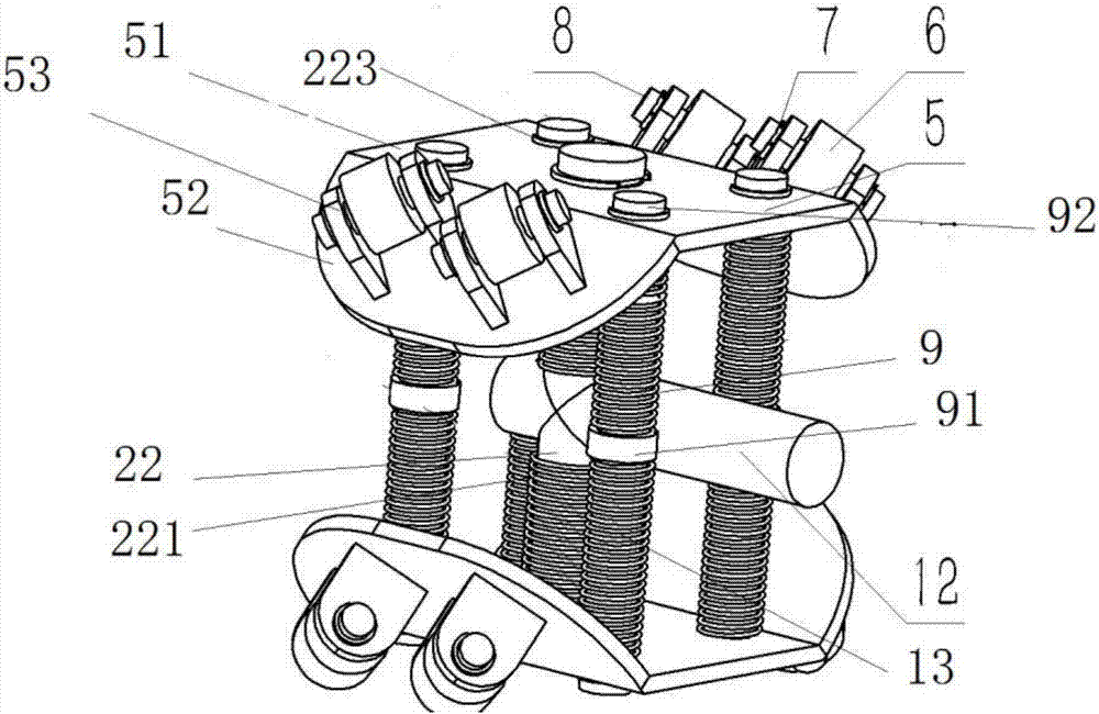
[0036] see figure 2, the roller bracket 5 is installed on the rotating shaft 12 through the fixing part 22, and the roller bracket 5 slides up and down along the fixing part 22; one end of the fixing part 22 is fixedly connected with the rotating shaft 12, and the other end of the fixing part 22 passes through the roller bracket 5 It is connected with the fixing member stopper 223; the spring 221 is sleeved on the outside of the fixing member 22, and the spring 221 is a compression spring, and the elastic force of the spring 221 keeps the roller bracket 5 away from the rotating shaft, so that the roller bracket 5 is pressed along the pipe wall of the pipeline 100 Walking; the fixed block 223 is used to prevent the roller bracket 5 from popping out of the fixed member 22 under the action of the spring 221;
[0037] The two roller brackets 5 symmetrically distributed along the rotating shaft are also connected by a guide post 9, and the two ends of the guide post 9 respectively...
Embodiment 2
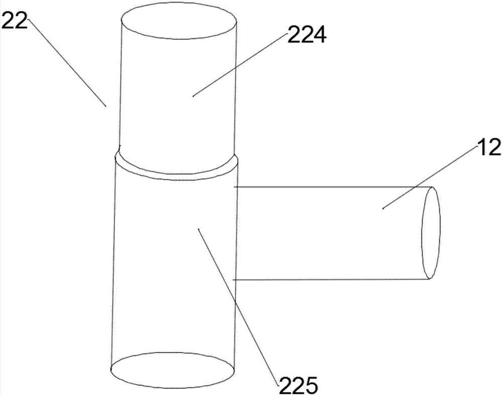
[0040] see image 3 , the fixed part 22 includes a telescopic part 224 and a telescopic part sleeve 225, the interior of the telescopic part sleeve 225 is hollow, the telescopic part 224 is inserted into the telescopic part sleeve 225, and the shaft between the telescopic part 224 and the telescopic part sleeve 225 Sliding and fixed fit in the circumferential direction; a spring is arranged in the sleeve 225 of the telescopic element, and the spring end is fixed on the bottom end of the inner wall of the sleeve 225 of the telescopic element, and the other end of the spring is fixedly connected with the telescopic element 224; the spring drives the telescopic The telescoping piece 224 is far away from the telescoping piece casing 225;
Embodiment 3
[0042] see Figure 4 , the two ends of the fixed part 22 are respectively fixedly connected with two roller brackets 5 symmetrically distributed along the rotating shaft 12, the fixed part 22 includes a telescopic part 224 and a telescopic part sleeve 225, and the inside of the telescopic part sleeve 225 is hollow, stretchable Part 224 is inserted into the telescopic part sleeve 225, and the telescopic part 224 and the telescopic part sleeve 225 are axially slid and circumferentially fixedly matched; the telescopic part sleeve 225 is provided with a spring, and the spring end is fixed on the telescopic part sleeve The bottom end of the inner side wall of 225, the other end of spring is fixedly connected with telescopic part 224; Spring drives telescopic part 224 and telescopic part sleeve pipe 225 away;
[0043] see Image 6 and Figure 7 , in the schematic diagram of the present invention in the pipeline, the driving wheel 6 forms a fixed angle with the axis of the pipeline...
PUM
 Abstract
Description
Claims
Application Information