Electric-driven three-jaw chuck

A three-jaw chuck and electric drive technology, applied in the field of mechanical processing, can solve the problems of difficult realization and control of lathe automation, and achieve the effect of simple structure, strong practicability and convenient operation

Active Publication Date: 2017-09-15
ANHUI UNIV OF SCI & TECH
View PDF4 Cites 0 Cited by
  • Summary
  • Abstract
  • Description
  • Claims
  • Application Information

AI Technical Summary

Problems solved by technology

[0002] As we all know, the three-jaw chuck is the most commonly used fixture in the field of mechanical processing. Whether it is a traditional lathe or a modern CNC lathe, the three-jaw chuck is an indispensable component. At present, the clamp of the three-jaw chuck There are mainly manual and hydraulic forms of tightening and loosening, which makes it difficult to realize and control the automation of lathes.

Method used


Image

  • Electric-driven three-jaw chuck
  • Electric-driven three-jaw chuck
  • Electric-driven three-jaw chuck

Examples


Embodiment Construction

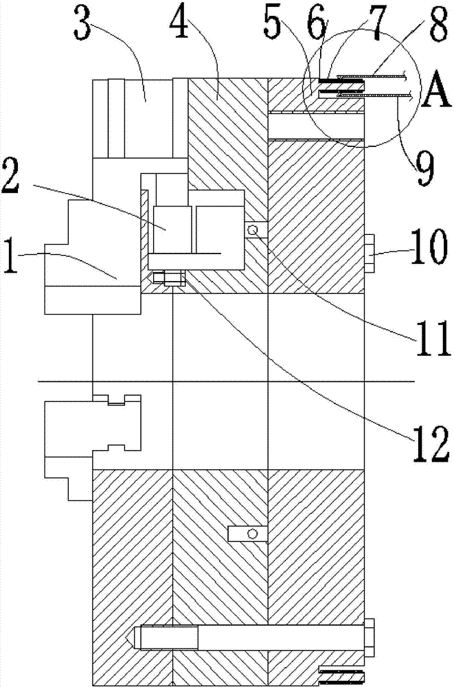
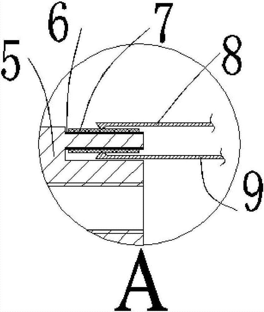
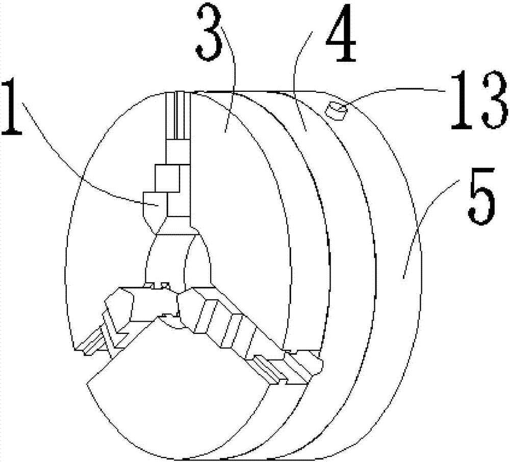
[0017] Such as figure 1 , figure 2 , image 3 , Figure 4 , Figure 5 , Image 6 , Figure 7 , Figure 8 , Figure 9 with Figure 10 The present invention described in the shown invention discloses an electrically driven three-jaw chuck, comprising jaws 1, electric cylinder 2, front chuck 3, middle chuck 4, rear chuck 5, insulating ring 6, slide Ring 7, positive electrode brush 8, negative electrode brush 9, bolt I10, wire 11, bolt II12, switch 13 and balance pin 14, characterized in that: the claws 1 are arrayed axially along the left end of the front chuck 3, and The movable pair is connected between the jaw 1 and the front chuck 3, the upper end of the jaw 1 is provided with a jaw baffle 101, the two sides of the jaw 1 are provided with a rectangular groove 102; the center of the front chuck 3 is provided with a through hole I302, one side of the front chuck 3 has three I-shaped guide rail grooves 301 in an axial array along the outer circle of the through hole I3...


PUM


Abstract

The invention discloses an electric-driven three-jaw chuck. The electric-driven three-jaw chuck comprises clamping jaws, an electric cylinder, a front chuck, a middle chuck, a back chuck, an insulation ring, a slide ring, a positive pole electric brush, a negative pole electric brush, a bolt I, an electric wire, a bolt II, a switch and a balance pin; three clamping jaws are axially arrayed at the left end of the front chuck; the clamping jaws and the front chuck are connected by a mobile pair; the middle chuck is positioned at the right end of the front chuck; the electric cylinder is positioned between the front chuck and the middle chuck; the back chuck is positioned at the right end of the middle chuck; the insulation ring is positioned at the periphery of the back chuck; the slide ring is positioned on one side, not contacted with the back chuck, of the insulation ring; the electric wire is positioned in the right end of the middle chuck; the positive pole electric brush is positioned on the outer side of the slide ring; the negative pole electric brush is positioned on the inner side of the slide ring; the switch is mounted on the peripheral edge of the back chuck; the balance pin is mounted on the peripheral edge of the back chuck; and the switch and the balance pin are centrally symmetrical about the back chuck. The electric-driven three-jaw chuck has the characteristics of convenience in operation, simple structure and high practicability.

Description

technical field [0001] The invention relates to the technical field of machining, in particular to an electrically driven three-jaw chuck. Background technique [0002] As we all know, the three-jaw chuck is the most commonly used fixture in the field of mechanical processing. Whether it is a traditional lathe or a modern CNC lathe, the three-jaw chuck is an indispensable component. At present, the clamp of the three-jaw chuck There are mainly manual and hydraulic forms of tightening and loosening, which makes it difficult to realize and control the automation of lathes. Therefore, there is an urgent need for a three-jaw chuck with convenient operation, simple structure and strong practicability, that is, an electrically driven three-jaw chuck, which can realize the electric control of the three-jaw chuck. Contents of the invention [0003] In order to overcome the disadvantages of the above-mentioned prior art, the present invention provides an electrically driven three-...

Claims


Application Information

Patent Timeline
Patent Type & Authority Applications(China)
IPC IPC(8): B23B31/103
CPCB23B31/103
Inventor 王传礼冒鹏飞陈明亮徐彬周大伟杨林建秦亚洲
Owner ANHUI UNIV OF SCI & TECH
Why Eureka
Try Eureka