Electric vehicle pedal-braking device and control method thereof

A braking device, electric vehicle technology, applied in bicycle accessories, transportation and packaging, bicycle brakes, etc., can solve problems such as potential safety hazards, and achieve the effects of safe and reliable braking, simple braking action, and good safety effect.

Inactive Publication Date: 2017-09-15
赖建君
View PDF9 Cites 0 Cited by
  • Summary
  • Abstract
  • Description
  • Claims
  • Application Information

AI Technical Summary

Problems solved by technology

[0002] In the existing electric vehicles, the common braking devices are generally manual pull-wire brakes, and the manual pull-wire brake components are generally installed on the leading handlebar of the electric vehicle. When the driver needs to brake, he not only needs to control the direction with both hands, but also It is necessary to hold the brake lever tightly, which will inevitably cause certain safety hazards in a hurry; in addition, the current manual pull-wire brakes are not very good for the development trend of consumers pursuing miniaturization, aesthetics, and folding of electric vehicles. to solve the needs of users

Method used


Image

  • Electric vehicle pedal-braking device and control method thereof
  • Electric vehicle pedal-braking device and control method thereof
  • Electric vehicle pedal-braking device and control method thereof

Examples


Embodiment Construction

[0039] Embodiments of the present invention will be described in detail below.

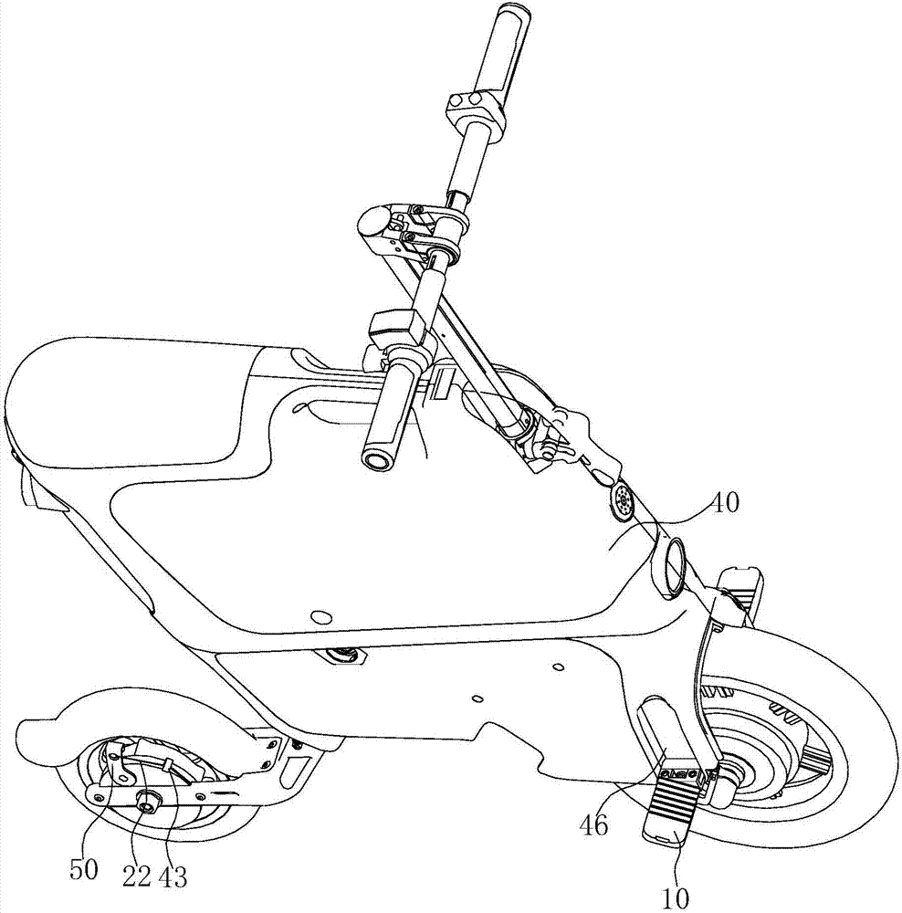
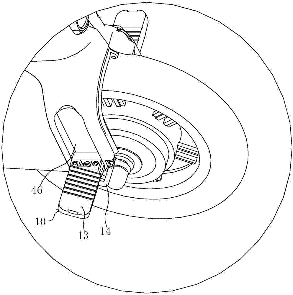
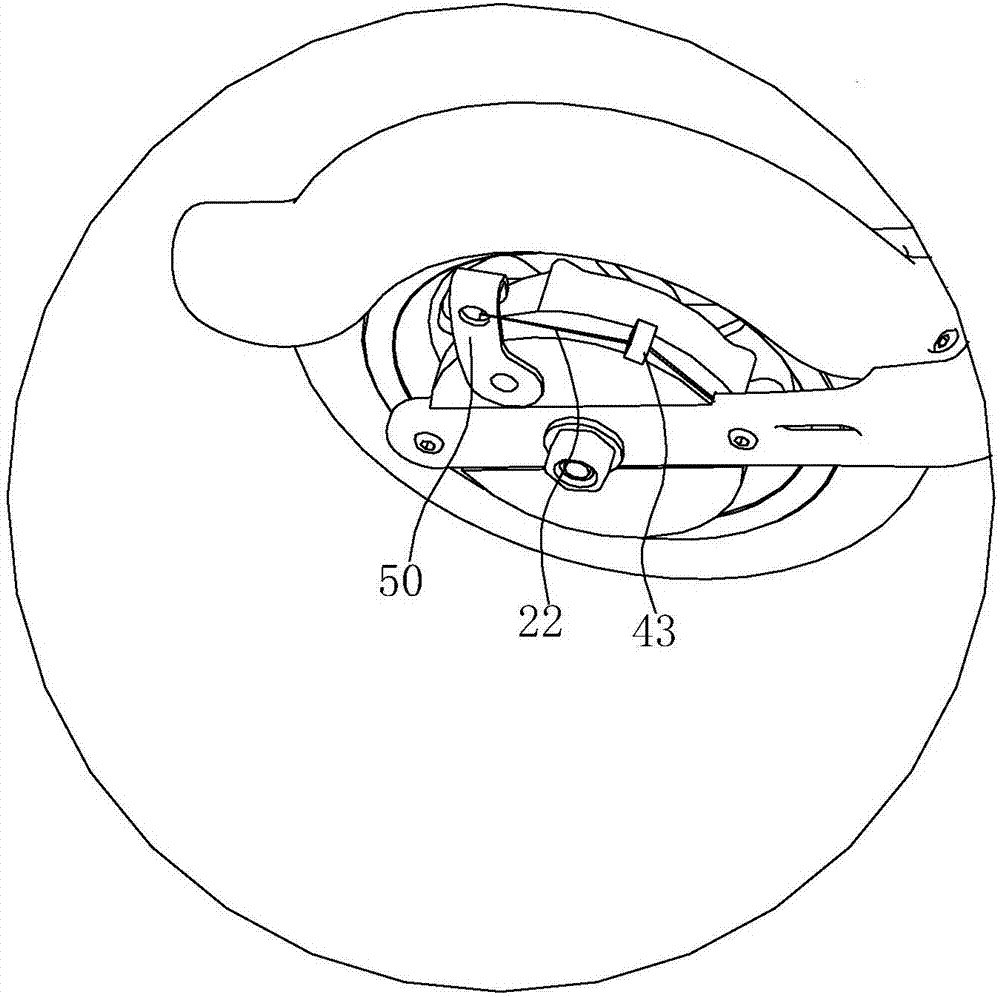
[0040] Such as Figure 1 to Figure 9 As shown, the pedal brake device for an electric vehicle includes a brake pedal 10 and a brake line 20. The brake pedal 10 is provided with a first rotating shaft 30, and the brake pedal 10 is rotationally connected with the vehicle body 40 through the first rotating shaft 30. The upper surface of the brake pedal 10 has On the laying surface, the brake pedal 10 has a pulling portion 11 , and the pulling portion 11 of the brake pedal 10 is connected to the vehicle braking component 50 through a brake wire 20 .

[0041] Wherein, the vehicle body 40 is provided with an adapter 41, and the first rotating shaft 30 is connected with the vehicle body 40 through the adapter 41. The adapter 41 is provided with a first through hole 411, and the position of the first through hole 411 is the same as that of the first rotating shaft 30. Correspondingly, the first through h...


PUM


Abstract

The invention discloses an electric vehicle pedal-braking device. The electric vehicle pedal-braking device comprises a braking pedal and a braking cable. The barking pedal is provided with a first rotating shaft, and the braking pedal is rotatably connected with a vehicle body through the first rotating shaft. A putting surface is arranged on the upper surface of the baking pedal, the braking pedal is provided with a pulling part, and the pulling part of the braking pedal is connected with a vehicle barking part through the braking cable. A control method of the electric vehicle pedal-braking device includes the steps that when a vehicle runs normally, feet of a rider is put on the putting surface of the braking pedal; when the vehicle needs braking, the braking pedal is stamped by the rider, the pulling part of the braking pedal is rotatably pulled downward with the first rotating shaft as the center, thus the barking cable is driven to pull the vehicle braking part, and the electric vehicle is stopped. According to the electric vehicle pedal-braking device, braking of the electric vehicle can be achieved by stamping the braking pedal, movement of stamping of the braking pedal is simple and convenient, and braking is safe and reliable.

Description

technical field [0001] The invention relates to a brake device, in particular to a pedal brake device for an electric vehicle and a control method thereof. Background technique [0002] In the existing electric vehicles, the common braking devices are generally manual pull-wire brakes, and the manual pull-wire brake components are generally installed on the leading handlebar of the electric vehicle. When the driver needs to brake, he not only needs to control the direction with both hands, but also It is necessary to hold the brake lever tightly, which will inevitably cause certain safety hazards in a hurry; in addition, the current manual pull-wire brakes are not very good for the development trend of consumers pursuing miniaturization, aesthetics, and folding of electric vehicles. to solve the needs of users. Contents of the invention [0003] The object of the present invention is to provide a pedal brake device for an electric vehicle, which can realize the braking of...

Claims


Application Information

Patent Timeline
IPC IPC(8): B62L3/04B62J6/16
CPCB62J6/16B62L3/04
Inventor 赖建君
Owner 赖建君
Why Eureka
Try Eureka